9. Interfaces
9-2 Technical Manual for sunrise RC, TW, TS, TC, BC, 6F No. T 137 302 Rev No. 1.1 2004-10
9.1.3 RS-232-C Interface Lines
The serial interface of the instrument is connected to a start-stop synchronized
serial RS-232-C circuit.
The list below names the interface lines of the 9 pin connector of the instrument.
PIN Number DESCRIPTION
1 N.C.
2 TD Transmit Data (Output)
3 RD Receive Data (Input)
4 N.C.
5 GND Ground
6 N.C.
7 RTS Request To Send (Output)
8 CTS Clear To Send (Input)
9 N.C.
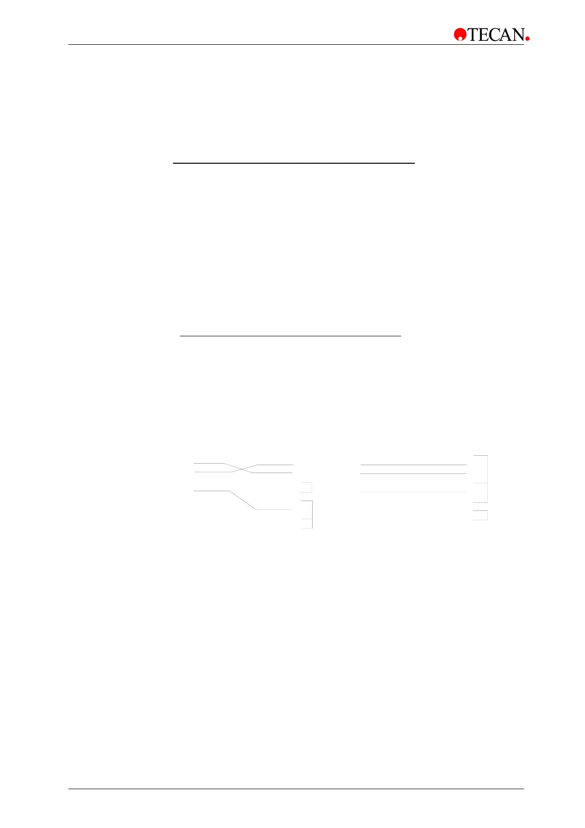
The connecting cable used to connect the instrument to the computer should be
wired as given below:
INSTRUMENT COMPUTER
TD connected to RD
RD connected to TD
GND connected to GND
RTS connected to CTS
DSR connected to DCD and DTR
Use the computer handbook to find the correct pin connections.
1
2
3
4
5
6
7
8
9
1
2
3
4
5
6
7
8
9
1
2
3
4
5
6
7
8
9
1
2
3
4
5
6
7
8
20
Instrument InstrumentComputer 25 pin Computer 9 pi
Requirements for the Serial Interface:
Computer interface 300-38.400 baud.
Download of new FW versions (FW-Update).
Remote control.
Download of test definitions.
Download of gradient wavelength table values.
Download of QC-Pac2 norm data.
General packet frame: STX
packet ETX CS CR.
Spectra Mode available


 To Next Page