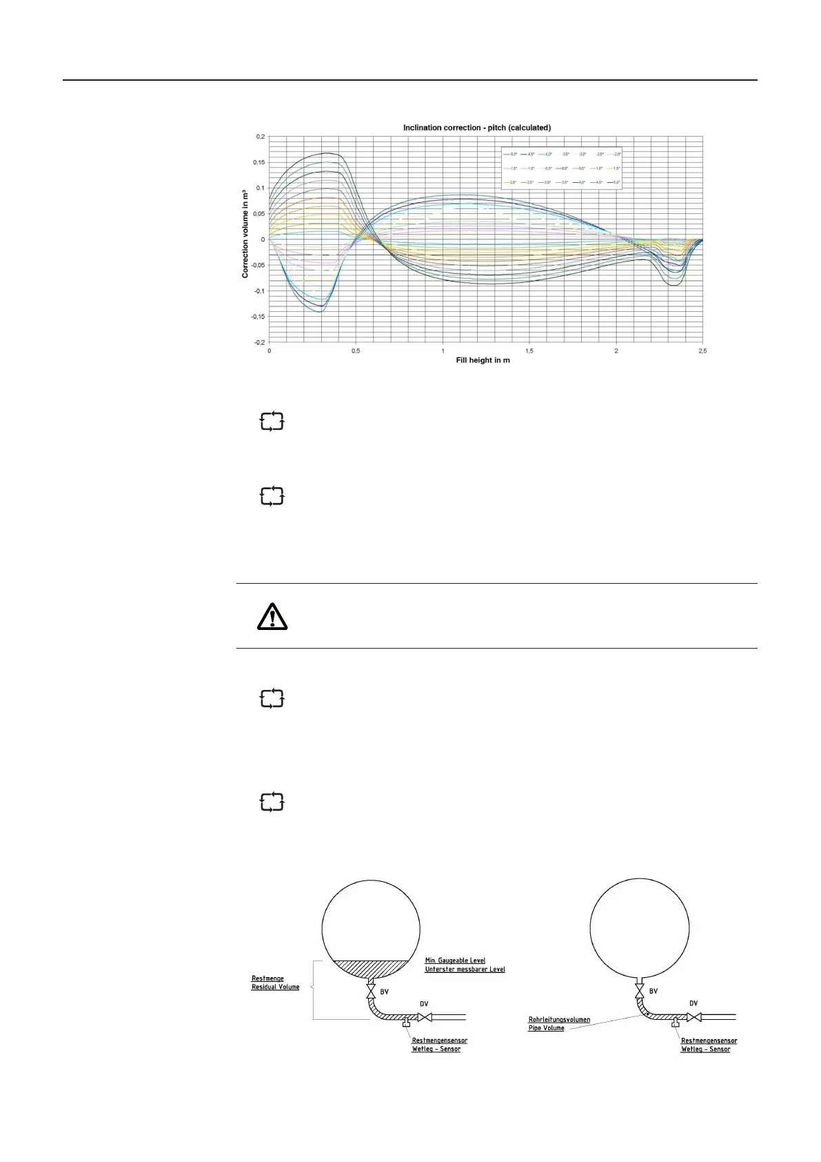
Figure 6: Typical inclination correction curves
The calibration limit of the absolute inclination correction values is determined
by the accuracy of the angle sensor. If the correction values become too large
in relation to the size of the compartment, the error due to the angle sensor
exceeds the calibration limits and the compartment can no longer be calibrated.
A deviation of the level sensor from the target position due to manufacturing
tolerances also produces a measuring error. Compensation is possible within
limits by means of the computational shifting (X/Y shift) of the level sensor to its
ideal position. However, in this case also there is an additional error due to the
ATTENTION:
Level sensor measuring compartments place stricter demands on the
manufacturing tolerances. The more precise manufacturing is, the simpler
in the piping measured by the level sensor. Therefore, the residual quantities
way, once the tank compartment has been emptied to the extent that the
As soon as the level falls below the measurable range, no further quantity
is added to that already indicated. The residual volume is only added to the
delivery quantity when the wet leg sensor becomes dry at the end of the
in the following diagram.
Figure 7:
MultiLevel Instruction Manual Description of the Level Gauging System
Drawing 73-WM-008