SPAZIO FORMA: Service & Maintenance manual - rev. 1.0
Page 6.27
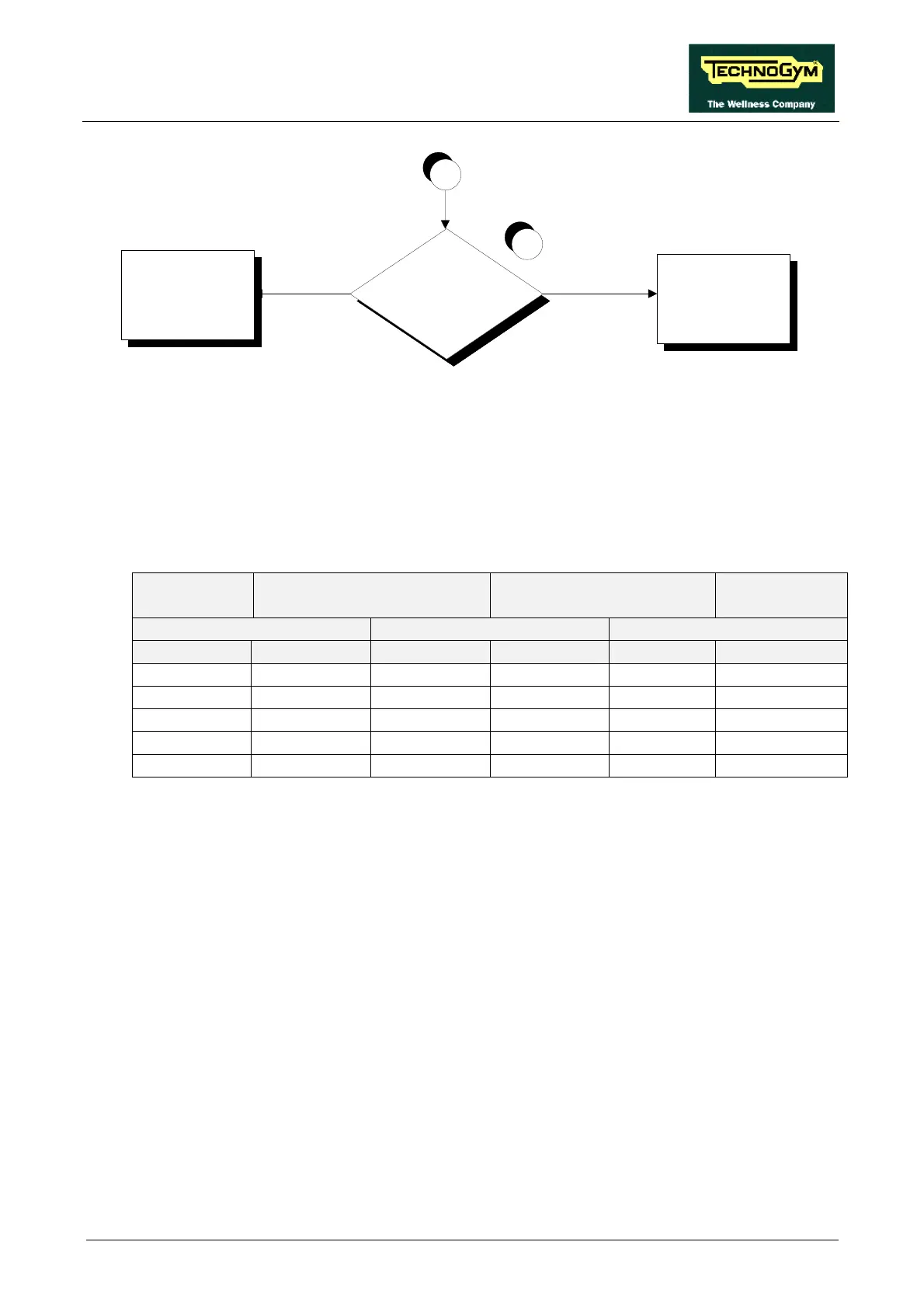
Is the inv erter control PWM
signal at the output of the
CPU board correct?
A
YES
Check and/or replace
cables SF-21A and/or
SF-12
Replace the CPU board
NO
6
Follow the procedure step by step to correctly diagnose the problem. Take particular care with the
checks highlighted by circled numbers, which are described in detail below:
(1) See paragraph 9.5. to set the inverter and 8.6. to regulate the speed.
(2) When the machine is in operation, check that the speed shown on the display and the inverter
operating frequency are approximately those shown in the table below.
SPEED
(Km/h)
PWM SIGNAL
(Vdc)
ANALOG SIGNAL
(Vdc)
FREQUENCY
(Hz)
CPU BOARD DRIVER BOARD INVERTER
DISPLAY 4-12/K4 4-12/J6 5-6/J5 O-L DISPLAY
1.0 4.68 4.68 0.56 0.56 5.3
4.0 3.84 3.84 2.42 2.42 19.6
8.0 2.70 2.70 4.90 4.90 39.8
12.0 1.56 1.56 7.38 7.38 60
16.0 0.42 0.42 9.85 9.85 80
Table 6.7-1
(3) Place the tester probes between the 0 (signal) and L (ground) terminals of the inverter. Check
that during machine operation the speed shown on the display and the voltage measured on
the inverter correspond the values shown in Table 6.7-1.
(4) Place the tester probes between pins 5 (signal) and 6 (ground) of connector J5 on the driver
board. Check that during machine operation the speed shown on the display and the voltage
measured on the inverter correspond the values shown in Table 6.7-1.
(5) Place the tester probes between pins 4 (signal) and 12 (ground) of connector J6 on the driver
board. Check that during machine operation the speed shown on the display and the voltage
measured on the inverter correspond the values shown in Table 6.7-1.
(6) Place the tester probes between pins 4 (signal) and 12 (ground) of connector K4 on the CPU
board. Check that during machine operation the speed shown on the display and the voltage
measured on the inverter correspond the values shown in Table 6.7-1.