14. Note and record the DMM reading, and then adjust the Model 2410 display to agree with
the DMM reading. Again, the maximum display adjustment is within ± 10% of the
present range.
15. After adjusting the display value to agree with the DMM reading, press ENTER and note
th
at the instr
ument displays:
I-CAL
Press ENTER to Output -0.0000μA
16. Press ENTER. The Model 2410 will source -0µA and simultaneously display the
following:
DMM RDG: +0.000000μA
Use , , ▲, ▼, ENTER, or EXIT.
17. Note and record the DMM reading, and then adjust the display to agree with the DMM
reading. Once again, the maximum adjustment is within ±1% of the present range.
18. After adjusting the display to agree with the DMM reading, press ENTER to complete
calibration
of the present range.
19. Press EXIT to return to normal display, and then select the 10µA source range using the
EDIT
and up RANGE keys. Repeat steps 2 through 18 for the 10µA range.
20. After calibrating the 10µA range, repeat the entire procedure for the 100µA through 1A
ran
ges
using Table 2-4 as a guide. Be sure to select the appropriate source range with the
EDIT and up RANGE keys before calibrating each range.
Model 2410
Digital Multimeter
Input LO
Amps
2410 SourceMeter
250V
PEAK
5V
PEAK
HI
LO
OUTPUT
1100V
PEAK
1100V
PEAK
EDIT
TOGGLE
POWER
RANGE
INPUT/
OUTPUT
SENSE
Ω 4 WIRE
DISPLAY
ON/OFF
TERMINALS
FRONT/
REAR
AUTO
RANGE
!
EXIT ENTER
CONFIG MENU
SWEEP
TRIG
REL
LOCAL
FILTER
LIMIT
DIGITS SPEED
V
Ω
MEAS
I
FCTN
V
I
SOURCE
230
1
67
89
4
+/-
5
STORE
RECALL
EDIT
2420 3A SourceMeter
®
4-WIRE
SENSE
2410 1100V SourceMeter
®
!
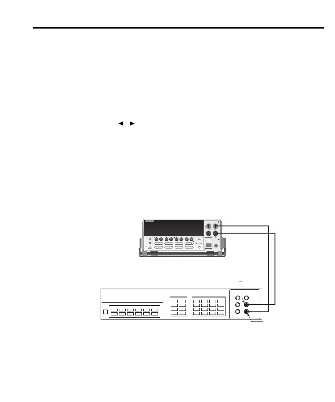
Figure 2-2
Current
calibration
test connections
Calibration 2-13
2410-902-01.book Page 13 Monday, November 7, 2005 2:49 PM