Analog Section
Output
A/D
Converter
Guard
Buffer
Guard
Display,
Keyboard
Microcomputer
Digital
I/O
GPIB
Interface
RS-232 I/O
GPIB I/O
Digital Section
To Analog
Circuits
To
Output Stage
To
Digital Circuits
±70V
±15V
+5V ±42V
±1200V +5V +12V
Analog
Power
Supply
Output
Stage
Power
Supply
Digital
Power
Supply
Line In
Power Supply
DACs
Clamps
Output
Stage
Feedback
Front
Panel
Controller
Trigger,
Digital
I/O
RS-232
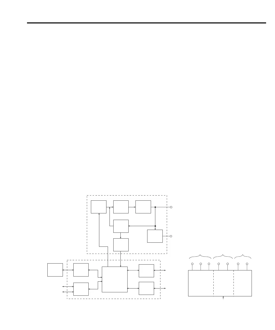
Figure 4-1
Overall
block diagram
Principles of operation
The following information is provided to support the troubleshooting tests and procedures
covered in this section of the manual. Refer to the following drawings:
Figure 4-1 — Overall block diagram
Figure 4-2 — Analog circuitry block diagram
Figure 4-3 — Power supply block diagram
Figure 4-4 — Output stage simplified schematic
Figure 4-5 — Digital circuitry block diagram
Overall block diagram
Figure 4-1 shows an overall block diagram of the Model 2410. Circuitry is divided into three
general areas:
• Analog circuits —
includes circuits such as the DACs, clamps, output stage, and
feedback circuits, as well as measurement circuits such as the A/D converter.
• Digital circuits — includes the microcomputer that controls the analog section, front
panel, and the GPIB and RS-232 ports, as well as associated interfacing circuits.
• Power supplies — converts the AC line voltage into DC voltages that supply the power
for the digital and analog circuits, and the output stage.
Troubleshooting 4-5
2410-902-01.book Page 5 Monday, November 7, 2005 2:49 PM