Analog board removal
Perform the following steps to remove the analog board. This procedure assumes that the case
cover is already removed.
1. Disconnect the front and rear input terminals.
You mu
st disconnect these input terminal connections for both the front and rear inputs:
• INPUT/OUTPUT HI and LO
• 4-WIRE SENSE HI and LO
• V, Ω, GUARD, and GUARD SENSE (rear panel only)
Remov
e all the connections by pulling the wires off the pin connectors, and then remove
the ferrite n
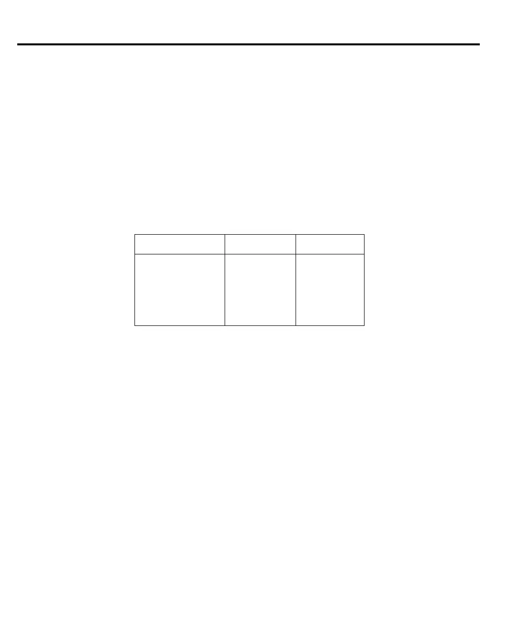
oise filters from the chassis. During reassembly, use the following table to
identify input terminals:
2. Unplug cables.
• Carefully unplug the ribbon cables at J1001, J1002, and J1003.
• Unplug the ON/OFF cable at J1034.
3. Remove screws.
• Remove the two fastening screws that secure the analog board assembly to the chas-
sis. These screws are located on the side of the board opposite from the heat sink.
• Remove the two screws that secure the heat sink to the chassis.
4. Remove analog board assembly.
• After all screws have been removed, carefully lift the analog board assembly free of
the main chassis.
5. Disass
emble analog board assembly.
• Remove the screws that secure the analog board and heat sink to the analog board
subchassis.
• Carefu
lly remove the heat sink by sliding the clips off the power transistors.
CAUTION Be
caref
ul not to damage the heat sink insulation layer.
• Remove the analog board from the subchassis.
• Remove the four screws that secure the bottom cover, and then remove the cover from
the bo
ttom of the PC board.
NOTE When re
-installing the heat sink, make sure all clips are properly installed and cen-
tered on each pair of output transistors.
Terminal Front wire color Rear wire color
INPUT/OUTPUT HI
INPUT/OUTPUT LO
4-WIRE SENSE HI
4-WIRE SENSE LO
V, Ω
, GUARD
GUARD SENSE
Red
Black
Yellow
Gray
—
—
White/Red
White/Black
White/Yellow
White/Gray
White
Blue/White
5-6 Disassembly
2410-902-01.book Page 6 Monday, November 7, 2005 2:49 PM