p
Model 880 DEPOSITION CONTROLLER
y
SECTION 3.XX
e page 101 of 275 ^
SECTION 3.13
Film Phases and Parameter Groups
There are several phases during a deposition layer of the Model 880 related to the source and
deposition rate control. There are three main parts to a deposition layer. These are pre-deposition,
deposition control, and post-deposition. The pre-deposition parameters control the source and material
conditioning prior to the film deposition. The Model 880 can control a variety of different types of
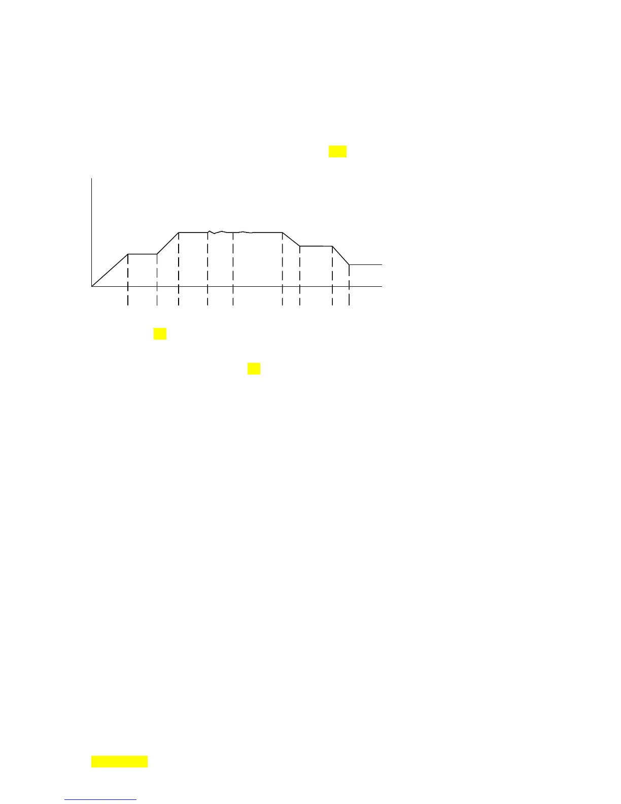
deposition sources. The typical run cycle shown in Figure 3.15 is for an E-B or thermal source.
Typical Film Deposition Cycle
Rise
1
Rise
2
Soak
1
Soak
2
Shutter
Delay
Deposit
Rate
Ramp
Deposit
2
Idle
Ramp
Idle
Figure- 3.15: Typical Run Cycle.
Table 3.1 which follows provides a list of phases and their associated parameters for all phases of
the deposition. There are also several film parameters which relate to the deposition material and sensor
calibration . Among these are DENSITY, Z FACTOR and TOOLING. A detailed description of each film
and map parameter is given in section 3.5. Indexing, if used, follows XTAL verify and precedes Rise 1.
Phase Parameters Group
RISE 1 SOAK 1 PWR VALUE Pre-Deposit
PWR RAMP 1 TIME
SOAK 1 PWR SOAK 1 TIME
RISE 2 SOAK 2 PWR VALUE
PWR RAMP 2 TIME
SOAK 2 PWR SOAK 2 TIME
SHUTTER DELAY SHTR DELAY MODE
SHTR DLY TIMEOUT
SHTR DLY QUALITY
DEPOSIT DEPOSIT RATE Deposition
CTL LOOP P
CTL LOOP I
CTL LOOP D
MAX POWER LIMIT
ABORT MAX PWR SW
MAX POWER DWELL
RATE RAMP RATE RAMP MODE Control
RATE RAMP TRGR
RATE RAMP TIME
NEW DEP RATE
DEPOSIT 2 NEW DEP RATE
IDLE RAMP PWR RAMP 3 TIME Post-Deposit
IDLE SOAK 3 PWR VALUE
Table 3.1: Model 880 Phases and Parameters.