p
Model 880 DEPOSITION CONTROLLER
y
SECTION 5.XX
e page 154 of 275 ^
Truth Table Notation
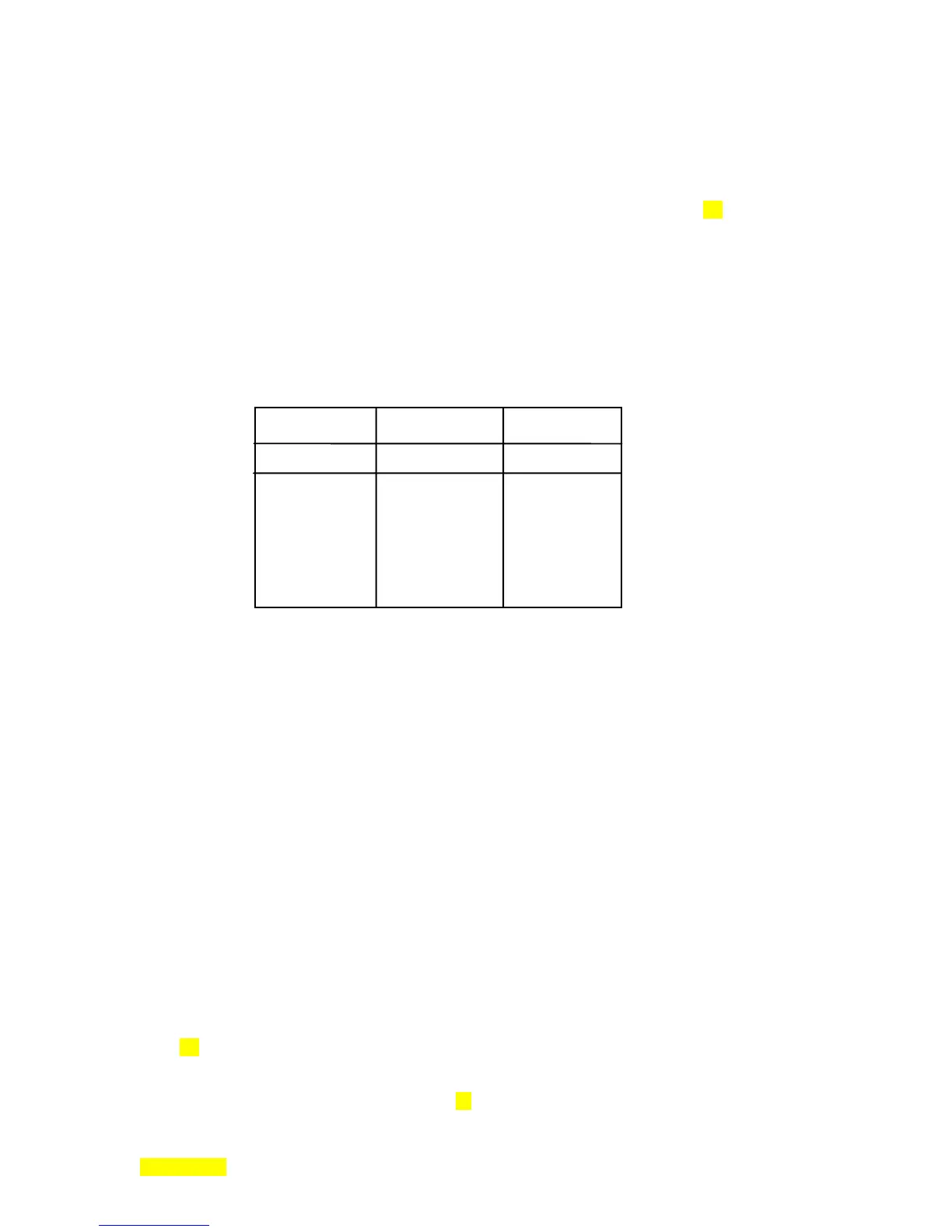
When using Boolean operators, it is common to use a truth table, (Refer to Table 5.3). This shows
all possible combinations of inputs and the resulting outputs. Let's assume that we have 2 input terms
called A and B, and the output term is called C. The operator symbols for 'AND', 'OR' and 'NOT' are
&
,
¦, and ! , respectively. For the following table, we will use TRUE (T) and FALSE (F) to indicate Boolean
states.
& (AND)
¦
(OR)
! (NOT)
A & B = C
A
¦
B = C
! A = C
T T T
T F F
F T F
F F F
T T T T F
T F T F T
F T T
F F F
Table 5.3: Truth Table.
Model 880 States and Events
You are already familiar with states of the Model 880. Some of them appear on the RunTime
screen and appear as large characters. Common states are STOPPED, DEPOSIT, RISE 1, etc. States are
just a period of time in which the Model 880 does a particular task. There are many internal states into
which you have access with the I/O program. It is not necessary to fully understand the internal workings
of the Model 880 in order to write an I/O program, however. By examining the examples later in this
section, you can get a good idea of what is needed.
State Diagram Notation
In writing an I/O program, you can test whether a state is active or not. Events cause something to
happen in the Model 880. An example of an event is pushing the START key. In state diagram notation,
events are the lines connecting states together. The I/O system can force events in the Model 880. Refer to
Table 5.4, a list of all of the states and events the I/O system can access. You may want to copy this table
and keep it handy as you go through the examples. It provides a key to the codes in an I/O program. Four
front panel LEDs (output) and four fixed front panel keys (input) have been assigned ID's which allow
them to be incorporated into an I/O program
(Table 5.6,#64-71)
.
SECTION 5.3