p
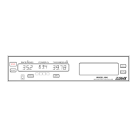
Model 880 DEPOSITION CONTROLLER
y
SECTION 2.XX
e page 38 of 275 ^
Power Soak 1 Time (@ pwr level) 0 to 99:59 MM:SS
Soak 2 Power level Value 0.0 to 100.0%
Power Ramp 2 Time (to pwr level) 0 to 99:59 MM:SS
Power Soak 2 Time (@ pwr level) 0 to 99:59 MM:SS
Soak 3 Power level Value 0.0 to 100.0%
Power Ramp 3 Time (to pwr level) 0 to 99:59 MM:SS
Control Loop –P-roportional term 1 to 9999
Control Loop –I-ntegral term 0.0 to 99.9 sec
Control Loop –D-erivative term 0.0 to 99.9 sec
Max Power Limit 0.0 to 100.0%
Abort Max Power SW OFF/ON
Max Power Dwell 0:01-99:59 MM:SS
Control Loop Qual Limits 0 to 9
Plot Vert Scale Volts 1, 5, 10, 50, 100 ⇐ Graphical display function
Plot Horiz Scale H 1 to 600 samples ⇐ Graphical display function
Data Plot Type Rate /Power /Rate Deviation ⇐ Graphical display function
Source Sensor Map Select 1 to 9
(Selects the Map that contains Source Sensor analog output parameters)
Etching Mode Off / On (
Rate Direction can be Positive or Negative)
The Power Related RunTime Screen parameters are:
(Crystal Quality Indicator Select) L/Q, Loop x, Qual xx
(Manual mode) (fixed front panel key)
(Manual mode) (pendant arrow keys [increase / decrease power manually])
(Manual mode) (2
nd
STATUS screen arrows: [increase/decrease power manually])
(Manual mode) (1
st
STATUS screen: zero power key [LCD] on non-active channels)
(Manual mode)
(2
nd
STATUS screen: zero thick key [LCD] no effect on material thickness)
(Manual mode) (2
nd
STATUS screen: force fail key [LCD] fail/verify crystal channels)
The Power Related System Configuration values are:
Menu path: Main/Executive menu/System Configuration]
Recorder Functions Rate, Rate Deviation, Power, Thickness, Computer Remote, I/O, Off
Recorder Analog Output ChaNneL
1 to 8 Channels (select 1 only)
[note possible conflict w/ Source Analog Output]
Need Source / Sensor Card x on/off
The Power Related Review Source Sensor Map values are:
Menu path: Main/Review SS Map]
Source FS Voltage Scaling PoWeR*
2.5/5/10 Full Scale VOLTS ⇐
see Power Supply input requirement
Source Max PoWeR 0.0 – 100.0%
Source Analog Output CHaNneL 1 to 8 Channels (select 1 only)
The Power Related Service Menu values are:
Menu path: Main/Service]
(Memory Contents) as is (no modification), purged, factory (defaults) [see section x3.21x ]
note film parameter changes
(Reset) Arm reset, reset armed [Provide a product reset when back panel power
switch is not accessible. Also, use to generate ACCEPT key if not
present (e.g. to end the Test mode when in the Test mode).]
*NOTE: Of primary concern when connecting evaporant power supply to the sensor card.
Dependencies
[Prerequisite states that must be in effect for the following parameters to be fully functional]
The Power Related Film Parameter Dependency List is:
Max Power Dwell Film Parameter: Abort Max Power SW = ON
These parameters are presented
here for the purpose of name
familiarization and categorization
of power related parameters
across menu and screen