p
Model 880 DEPOSITION CONTROLLER
y
SECTION 4.XX
e page 138 of 275 ^
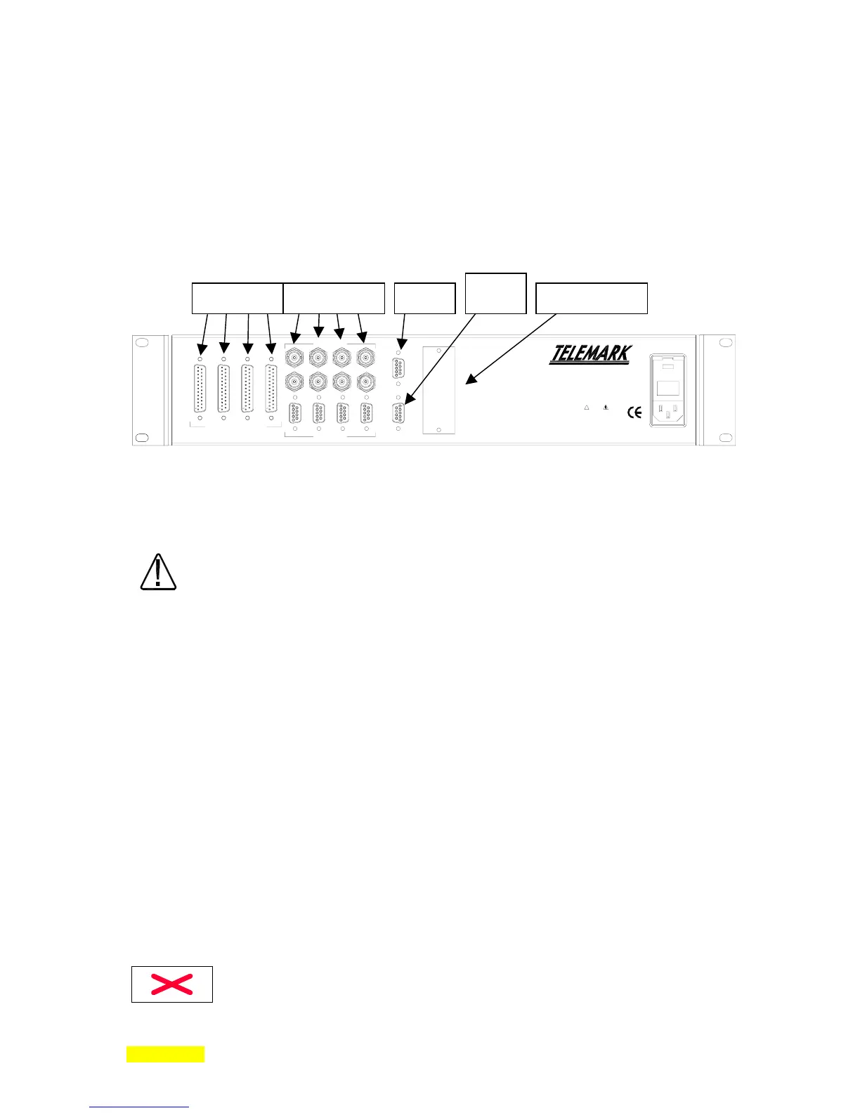
Electrical Connections and Descriptions
All electrical connections to the Model 880, with the exception of the remote hand held
power controller, are made at the rear panel of the instrument. Care should be exercised in
routing all cables as far as practically possible from any other cables or wires that may be
generating noise. These may include other line voltage cables, wires to heaters that are SCR-controlled,
and wires or cables to source power supplies that may conduct high transient currents during arc over
conditions.
I/O sensors/ctrl
WARNING
!
The power cord protective
grounding conductor must be
connected to ground. No user
serviceable parts inside. Refer
servicing to qualified personnel.
FUSE: 2 x 2.00 AMP
QUICK-ACTING (F) 250v
90-264 vac, 50-60 Hz, 230VA MAX
INPUTS / OUTPUTS
SOURCE
SENSORS
I/O 4 1/O 3 I/O 2 I/O 1
COMM OPTION
RS232
MEM
7 5 3 1
8 6 4 2
7 5 3 1
8 6 4 2
4.2: Rear Panel
Line Power
Line Power and Fuses
WARNING
Replace broken or blown fuses only with the ratings specified. Failure to do so may
result in unsafe operation and may cause damage to the unit. See back panel for fuse
specifications. Fuses are located in IEC power connector. (See section 7.1)
The Model 880 operates from 90 to 264VAC, 50/60Hz (
1.4A rms@120VAC, 0.7A rms@230VAC)
. No
adjustments are required. A correct IEC or Telemark power cord should be used.
Installation of Model 880 in a 19" Rack
To install a single Model 880 in a 19" rack it is recommended that the included mounting
ears be used.
Vacuum System Grounding
GROUND
SECTION 4.1
SECTION 4.2
SECTION 4.3
SECTION 4.4
4 3 2 1
RS232
MEMORY
MODULE
COMM OPTION
D
B A