p
Model 880 DEPOSITION CONTROLLER
y
SECTION 2.XX
e page 48 of 275 ^
How to Develop I/O Programs:
This discussion may seem like a lot to absorb for unknown benefits. However, this short
introduction is needed to provide the user with the general I/O programming capabilities of the Model 880.
Once this is known, the system user need only run (or setup) their process until specific needs become
apparent. With a specific need in mind, a perusal of the Event and State ID List (Table x5.3) will match
your need to one or more of the many possible solutions within the expansive repertoire of the Model 880.
There has also been provided some example I/O programming segments with accompanying
explanations in section x5. These can be used to construct larger programs that fulfill the overall process
goal. Included with the Model 880 is a CD containing communications programs that allow the
construction of I/O programs on a P.C. Writing I/O programs in this way is further enhanced as comments
can be added using a comma as a delimiter and not having to use line numbers. The Windows® program
running on the P.C. will strip the comma and all that follows on each line and add the line numbers as the
I/O program is downloaded into the Model 880. I/O programs constructed on the Model 880 may also be
uploaded to a P.C. using the same communication program. The following is an example of such a program
constructed on a P.C. and from the P.C. view (this example [w/ checksum of 41779] is repeated with an
explanation in a later chapter).
I73 #2 = S8, Stopped Xtal bad sets relay 1 slot 2.
I228 C8, Begin Job/Film Event, clears relay 1 slot 2.
I79 #1 = O9, Source 1 shutter connects to relay 2 slot 2.
I81 #2 & O10, Sensor 2 shutter connects to relay 3 slot 2.
I221 S11, Setpoint thickness trigger sets relay 4 slot 2.
I228 C11, Begin Job/Film Event, clears relay 4 slot 2.
I0 T216, Input 1 slot 1 is start unconditional.
I0 T202,
I1 T200, Input 2 slot 1 is stop.
I2 T217, Input 3 slot 1 is final thickness trigger input.
I3 T219, Input 4 slot 1 is zero substrate thickness trigger.
I68 O64, Input function key 1 to front panel LED 1.
.running a deposition
test mode (introduce concept of, defer desc., user can test drive w/o danger)
run time mode: (concept of, text details only, implementation/screens deferred)
manual mode: (concept of, text details only, implementation/screens deferred)
non-sequencing mode (concept of, text details only, implementation/screens deferred)
deposition cycle (text 2.11)
product description (ch 2):
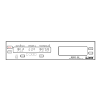
front panel desc. (2.1: last 2/3rds)
run time screen desc (2.3)
main menu desc (2.4)
navigating thru menus (2.2)
other main menu options (2.9).