p
Model 880 DEPOSITION CONTROLLER
y
SECTION 2.XX
e page 35 of 275 ^
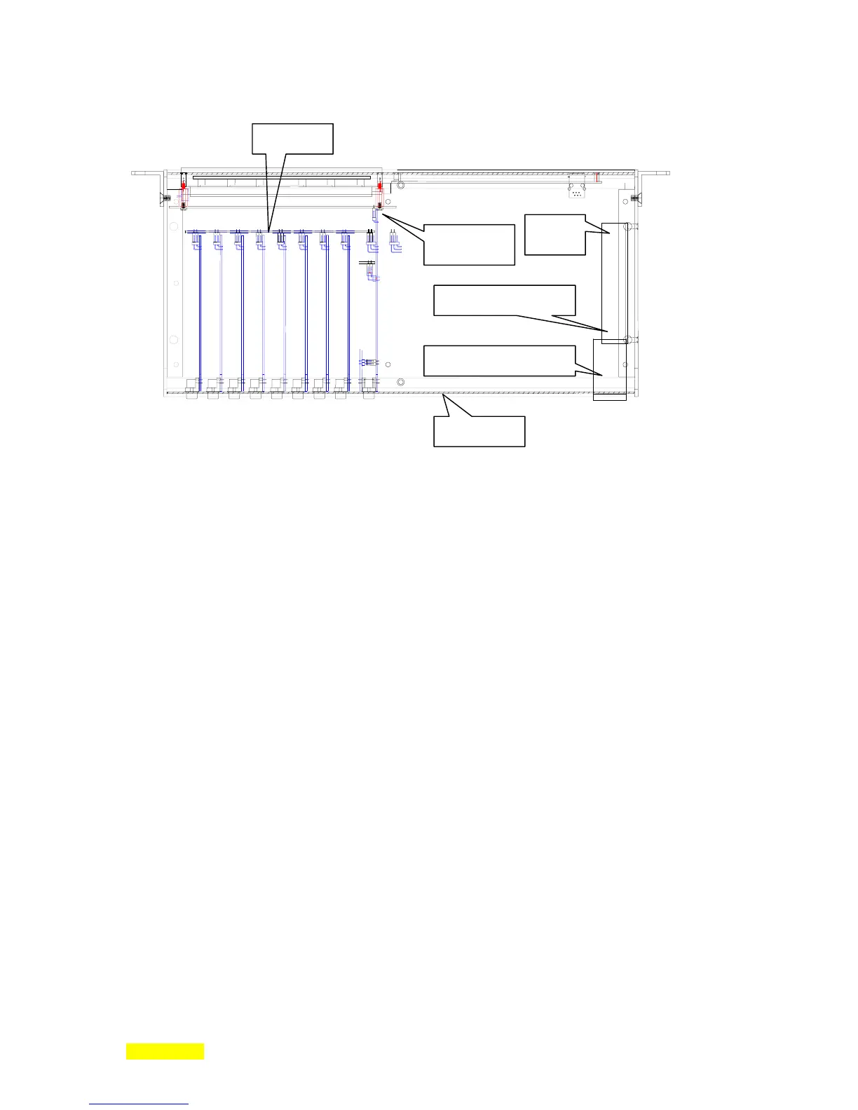
disconnects
h
r
bus board
power supply header
IEC switch/connector
back panel
DC
Header
Pendent:
Also called a hand controller,
may be connected by means of the front panel jack labeled Manual
Control when certain front panel functions need to be duplicated remotely or when intending to utilize the
Manual mode. When not in use, the pendent may be left plugged into the Model 880 unit or it may be
removed. The pendent does not contain any active electronics nor is it polled to check for its presence.
LCD contrast/bias: The optimal viewing is designed for perpendicular to about 45° up and about 45° from
perpendicular to either side. Within a few minutes of powering the unit on, there will be some thermal drift
effecting color but this should be relatively unnoticeable. If, however, the unit will be in an environment
having elevated ambient temperatures (above 30° Celsius), the LCD contrast/bias should be set to low
through menu programming (Main/Executive/System Configuration menus).
Graphical Display: Although no hardware other than the LCD display is associated with this item, it needs
to be setup. Three film parameters need to be programmed: Plot Vert Scale Volts, Plot Horiz Scale H, Data
Plot Type. The graphical display, as the name implies, displays, in graph form: rate deviation, rate or
power.
Rack Mounting: Rack mounting ears and screws are supplied with the Model 880 for the purpose of
mounting the unit in a standard rack.
Rubber Feet: Rubber feet are not supplied with the Model 880. The anticipated usage of the product is
within a rack. If, however, in the unlikely case where the usage will be on a shelf, table or some other flat
surface, rubber feet should be used to prevent sliding with the possible resultant damage. They should be
of the type that sticks on the bottom of the unit. These can be purchased cheaply at many retail outlets.
The waxed paper is first removed from each foot. The foot is then applied to the bottom of the Model 880
such that they are placed in each corner an inch from the 2 corner surfaces. Subsequently, if the unit will
be rack mounted, remove the rubber feet.
System Hardware Connections: Except for the generalized previous descriptions, complete system
hardware setup is beyond the scope of this manual. Consult the manuals for each of the components in the
system. The sum of the manuals is less than the whole: Be forewarned that the general information
contained herein is meant as an overview of the system only, an overview to describe how the Model 880
integrates with the other components in the system and some of its' typical usage's. The information