p
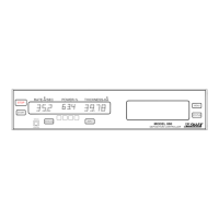
Model 880 DEPOSITION CONTROLLER
y
SECTION 5.XX
e page 186 of 275 ^
to: to:
Model 880 SRT-400
relay pins(F) pins(F)
6 -------------------- 1
17 ------------------ 2
3 -------------------- 7
14 ------------------ 3
7,18,4,15 --------- 6
input pins(M)
12 ------------------ 5
13 ------------------ 6
[see figure x4.3]
Entering The Program
For a little practice with counters or using the I/O, this program can be entered at the end of an
existing I/O program or in the alternate I/O memory and tested. Once installed, listen for the one second
click of relay 8 after every sixth push of the INC key on the hand control, and observe LED#2 either toggle
ON or OFF with each press of the INC key.
Example 4 - Fixed Delay & Pulse Width
The internal modulo 100 counters of the STC's I/O can easily be used along with the Time events
(ID# 1224 - once per second, ID# 225 - once per minute, ID# 226 once per hour) to generate a desired
pulse width after a fixed time delay after the occurrence of some internal or external event.
The Program
The following program implements a five second pulse on an output relay 50 seconds after the
occurrence of an external input to the Model 880.
1: I224 I400 #0 > & I68 P ¦ S400
2: I400 #50 > O15
3: I400 #55 > C400
4: I15 O65
Table 5.6: Fixed Delay & Pulse Width I/O Program
Rung By Rung
rung 1: is the rung which advances the ID# 400 counter. The first advance occurs on the positive edge of
the external input applied to remote Input 8 (ID# 07), once the counter is 'started' the once per
second event ID# 224 continues to advance the counter. [Change I68 to I7 to use an opto-input
instead of the programmable front panel key for input triggering method]
rung 2: Approximately 50 seconds later, when the counter reaches the value of 51, the second rung causes
Output Relay 8 to close (ID# 15).
rung 3: value of the comparison ">55" becomes True when the counter value exceeds 55, then the "C400"
resets the counter to the zero value state.
rung 4: copies the relay 8 state to LED#2.
Example 5 - I/O Program for Four Pocket Source
Input/Output assignments are as follows:
012 Relay 5, Pins 6(NO)&7(COM) of the RELAY OUTPUTS connector.
013 Relay 6, Pins 17(NO)&18(COM) of the RELAY OUTPUTS connector.
I7 Input 8, Pin 12(cathode) of the OPTOCOUPLER INPUTS connector
(assumes LED anode is pulled high via jumper headers JP1, JP2 and/or Pin 25 [see figure
x4.3]).
See Model 880 indexer described later
Model 880/SRT-400 Interconnect Cable: