3 MPH200 series video encoders WebUI user manual
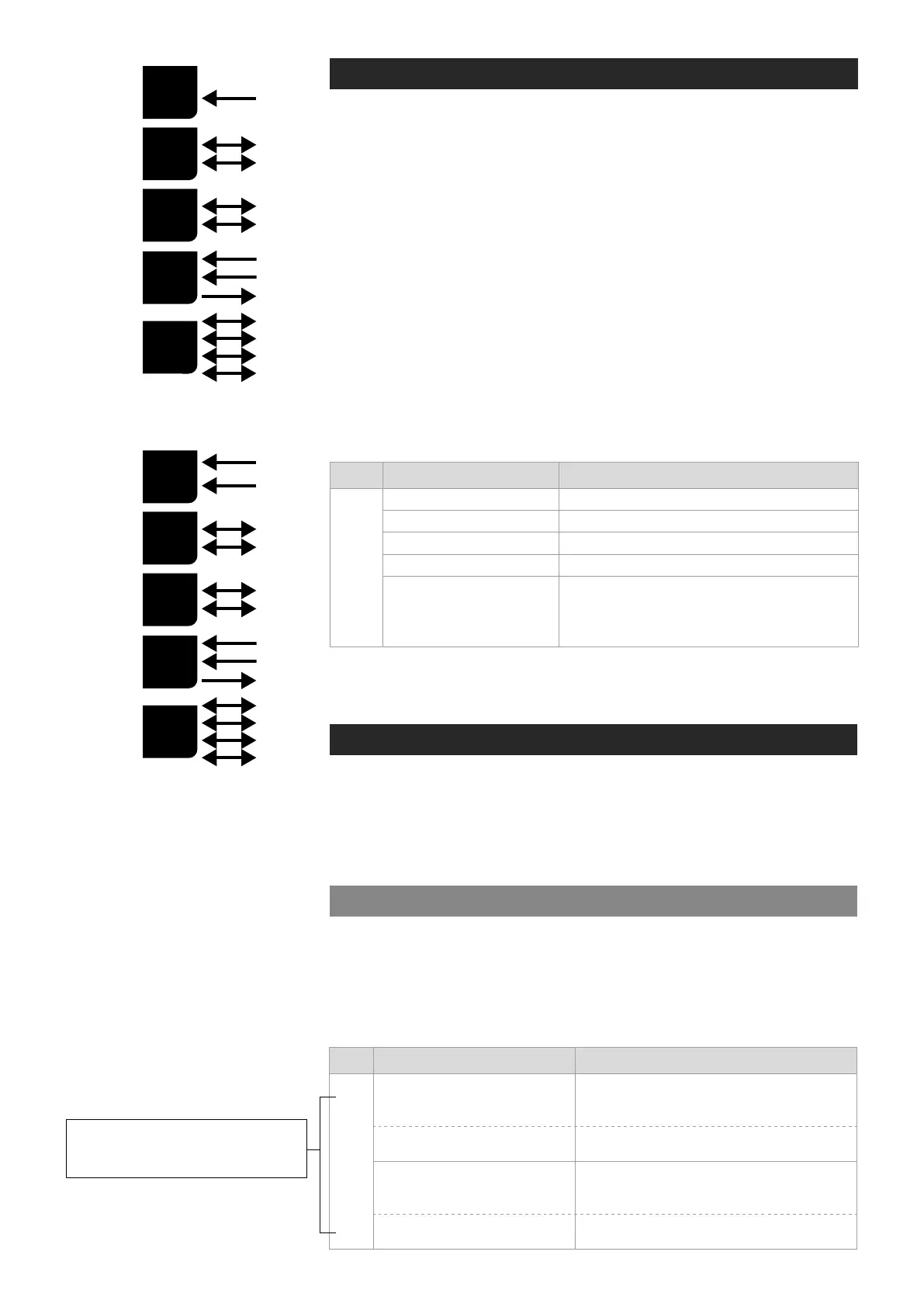
MPH200 series video encoders mechanical connections
1. CVBS video input 1, or optional HD-SDI video input (BNC female) and
indicator led.
2. CVBS video input 2
(BNC female)
for 2-ch versions or
Video loop through port for 1-ch versions and indicator led.
3. 16-pin screw terminal block and T indicator led:
Data interfaces, EIA RS422/485 (data1), EIA RS232 (data 2) /manage-
ment interface (CLI) or general purpose serial port.
Contact closure interfaces (cc input 1, cc input 2, cc output)
4. Ethernet switch up-link interfaces, 2 x socket for SFP module (GE,
see a product catalogue for supported models).
5. Ethernet switch local port interfaces, 2 x 10/100/1000Base-T, RJ-45.
6. Audio interface (10-pin screw terminal block).
7. Power supply connector (2-pin screw terminal block, +12...28 VDC).
Reset button: Device software reboot and hard/soft factory defaults
restoration (see section Factory reset).
Ground: Device ground connection.
M - (module/power led) LED indicator operation. This LED indicates power
status, factory reset, interface activity.
Factory reset
The factory reset can be done via WebUI, CLI, or using the pinhole reset
button on the front panel of device. There are two types of factory resets;
Soft factory and Hard factory reset. The Soft factory reset restores all,
except IP conguration to the default factory settings. The Hard factory
reset restores all settings to default factory settings.
Reset button
The reset pinhole is a button that resets the device to its original default
settings. To use this button, insert a stiff wire (such as a straightened paper
clip) into the pinhole. If you release the button immediately the device will
reboot with current settings. But if you hold the button you can restore the
default settings as following table shows.
Led Colour Mode
M
OFF / Dark Power off
Yellow Device starts up
Red Device self-test failed
Green Power on / Device is functional
Blinking Green
Device is being accessed from any interface.
Whenever device is accesed from WebUI, CLI or ONVIF
interface, led blinks 2s. During software update, LED will
blink throughout the rmware image transfer duration.
Led Colour Mode
M
6 x (short) green blinks at
boot time
Time window to select Soft factory reset.
If reset button is released in this time window, soft factory
reset is selected.
2 x (short) red blinks
Soft factory reset shall be applied.
Wait until device has fully started (power led green).
24 x yellow blinks at boot time
(after the 6 green blinks)
Time window to select Hard factory reset.
If reset button is released in this time window, hard
factory reset is selected.
4 x (short) red blinks
Hard factory reset shall be applied.
Wait until device has fully started (power led green).
Note! If pinhole button is not
released within time window,
operation will cancelled.
MPH241 signals.
MPH242 signals.
V
x2
D
x2
A
x2
C
C
x2
E
x4
V
x1
D
x2
A
x2
C
C
x2
E
x4