7 MPH200 series video encoders WebUI user manual
How to unplug or plug-in the SFP transceiver module
If your up-link port requirements change, simply unplug the existing SFP
module, and plug-in the new module. The SFP transceiver modules
must be installed before the encoder is powered on. Installing SFP:
1. Switch off the unit supply voltage.
2. Mount the SFP transceiver to the unit (see bottom instructions).
3. Connect the bre optic cable(s).
4. Ensure that the remote end of the bre is already connected to an
active switch.
5. Switch on the unit supply voltage.
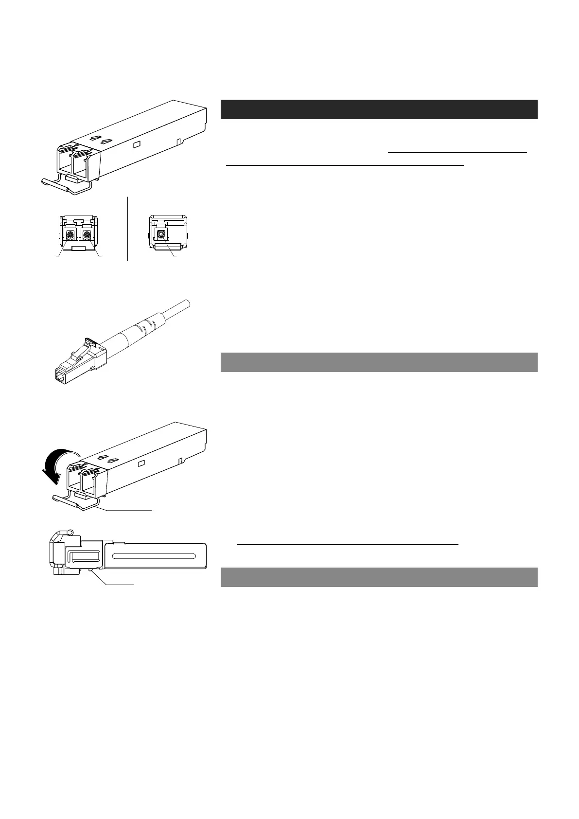
The SFP transceiver module has a bale-clasp latch that makes easier to
install or remove the module. Protect the SFP module by inserting a
clean dustplug into the module after you remove the ber cable. Be sure
to clean the optic surfaces of the ber cable before you plug the cable
into another module. When using 2 bre version SFP, select carefully
the correct optical port for TX and RX operation.
To unplug and plug-in the SFP module, follow these steps
1. Open the bale clasp on the SFP module by pressing the clasp
downward until it is in a horizontal position.
2. Use a small at-blade screwdriver or
other long, narrow instrument
to
push on the hinge pin to unlock the SFP cage latch.
3. Grasp the SFP module by the bale clasp and gently pull it out of the
SFP cage
.
To plug-in the module:
1. Orient the transceiver with the bale clasp on the bottom, close the
bale clasp by pushing it up over the transceiver, then gently insert
the transceiver into the port until it clicks into place.
Note! Reboot the device when the SFP is changed.
Some generic notes for successful optical connections:
• Ensure that the ber patch cord is damage-free (ber condition can
be easily checked by a visible laser tester)
• Do not exceed the minimum bending radius of the bre
• Avoid sharp corners on cable shelves and in cable management
in overall
• Make sure that correct optical connectors are used
• Open connectors are always secured by dustcaps during maintenance
• Always before mating clean all connectors (wet cleaning by high
purity alcohol & drying, or dry cleaning with reel-based lint-free wipes,
ber adapters may require special ferrule end-face cleaning tools)
• Before making any visual inspections ensure that system has been
shutdown or no optical power is present
• For fault nding at least a optical power meter is required, a complex
ber cable environment may require use of an OTDR equipment.
bale clasp
SFP module’s locking release points.
2 fibre version 1 fibre version
SFP plug-in optical transceiver module.
Optical connector is the type of LC.