11. A final check of boom alignment should be made by
“stringing” as described earlier and also by a visual in-
spection with the boom fully extended and at maximum
angle.
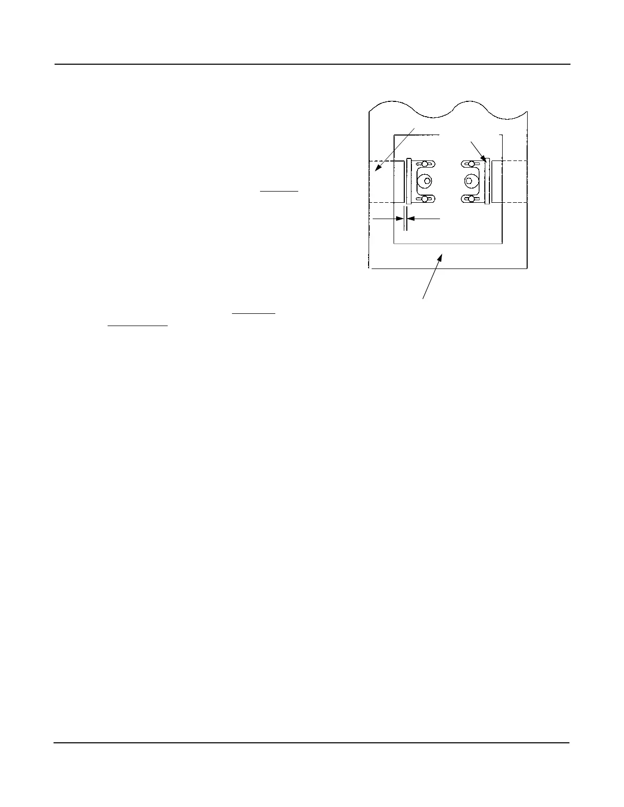
1/32 inch
BOOM TOP PLATE
PAD
ADJUSTMENT
BASE
5. Align the #3 boom section with the #2 boom section in the
same manner as step 4 by shimming and installing pads
“F”.
6. Align #4 (tip) boom section with the #3 boom section in
the same manner as step 4 by shimming and installing
pads “J”.
7. Shim and tighten pads “C”, “G”, and “K” to 1/32 inch
clearance between the pad surface and the boom section
on each side with the boom extended.
8. Grease the boom ahead of the wear pads.
9. Retract the boom, checking that no excessive binding oc-
curs.
10. Adjust the brackets on pads “A”, “E”, and “I” so the pads
contact the base boom section. Then “back off” until
there is 1/32 inch max clearance between the pad ad-
justment base and the pad. This must be done for the left
and right pad for each section. This will maintain a total
clearance of 1/16 inch. Tighten the lock bolts. This is
done with the boom retracted.
SERVICE & ADJUSTMENTS
6 - 9
Issued: August 2003RT700 Series