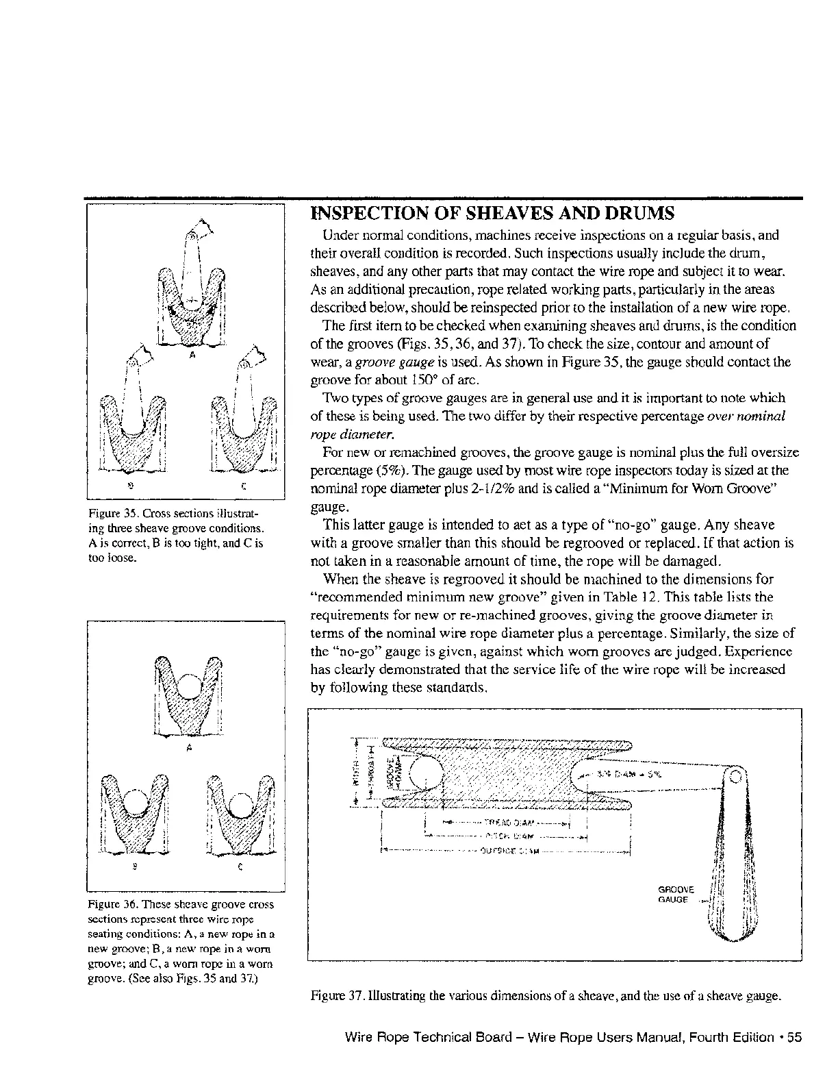
Figure 35. Cross sections illustrat-
ing three sheave groove conditions.
A is correct, B is too tight, and C is
too loose.
Figure 36. These sheave groove cross
sections represent three wire rope
seating conditions: A, a new rope in a
new groove; B, a new rope in a worn
groove; and C, a worn rope
in a worn
groove. (See also Figs. 35 and
37.)
INSPECTION OF SHEAVES AND DRUMS
Under normal conditions, machines receive inspections on a regular basis, and
their overall condition is recorded.
Such inspections usually include the drum,
sheaves, and any other parts that may contact the wire rope and subject it to wear.
As an additional precaution, rope related working parts, particularly in the areas
described below, should be reinspected prior to the installation
of
a new wire rope.
The first item to be checked when examining sheaves and drums, is the condition
of
the grooves (Figs. 35, 36, and 37). To check the size, contour and amount
of
wear, a
groove
gauge
is used. As shown in Figure 35, the gauge should contact the
groove for about
150
0
of
arc.
Two types
of
groove gauges are in general use and it is important to note which
of
these is being used. The two differ by their respective percentage over nominal
rope
diameter.
For new or remachined grooves, the groove gauge is nominal plus the full oversize
percentage (5%). The gauge used by most wire rope inspectors today is sized at the
nominal rope diameter plus 2-1/2% and is called a
"Minimum for Worn Groove"
gauge.
This latter gauge is intended to act as a type
of
"no-go" gauge. Any sheave
with a groove smaller than this should
be
regrooved
or
replaced.
If
that action is
not taken in a reasonable amount
of
time, the rope will be damaged.
When the sheave is regrooved it should be machined to the dimensions for
"recommended minimum new groove" given in Table 12. This table lists the
requirements for new
or
re-machined grooves, giving the groove diameter in
terms
of
the nominal wire rope diameter plus a percentage. Similarly, the size
of
the "no-go" gauge is given, against which worn grooves are judged. Experience
has clearly demonstrated that the service life
of
the wire rope will be increased
by
following these standards.
GROOVE
GAUGE
Figure 37. Illustrating
the
various dimensions of a sheave, and the
use
of a sheave gauge.
Wire Rope Technical Board - Wire Rope Users Manual, Fourth
Edition·
55