--t;~g",
I"
/1\
1 \
, \
I \
I \
I \
""""T"
--r---
FLO
AT
I N G
I
~SHEAVE
-7
r-
I \
I \
I \
I \
I \
I \
I \
I \
I \
I \
I \
I \
I \
I \
I 1/2.MIN
liZ·
MiN
\
I I 1/2·MAX
II/Z·
MAX
\
I \
r-;
.,,,
~~
1 LEFT
RIGHT
\
I FLEET FLEET \
I
ANGLE
ANGLE
\
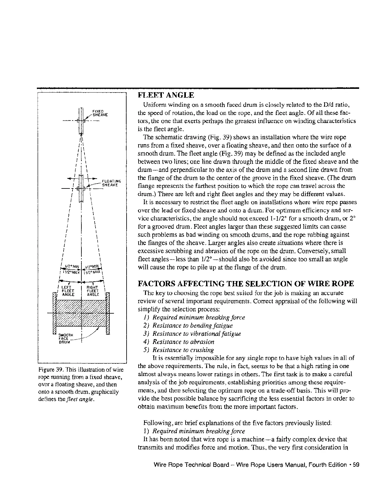
Figure 39. This illustration
of
wire
rope running from a fixed sheave,
over a floating sheave, and then
onto a smooth drum, graphically
defines the fleet angle.
FLEET ANGLE
Uniform winding on a smooth faced drum is closely related to the Did ratio,
the speed
of
rotation, the load on the rope, and the fleet angle.
Of
all these fac-
tors, the one that exerts perhaps the greatest influence on winding characteristics
is the fleet angle.
The schematic drawing (Fig. 39) shows an installation where the wire rope
runs from a fixed sheave, over a floating sheave, and then onto the surface
of
a
smooth drum. The fleet angle (Fig. 39) may be defined as the included angle
between two lines; one line drawn through the middle
of
the fixed sheave and the
drum-and
perpendicular to the axis
of
the drum and a second line drawn from
the flange
of
the drum to the center
of
the groove
in
the fixed sheave. (The drum
flange represents the farthest position to which the rope can travel across the
drum.) There are left and right fleet angles and they may be different values.
It is necessary to restrict the fleet angle on installations where wire rope passes
over the lead or fixed sheave and onto a drum. For optimum efficiency and ser-
vice characteristics, the angle should not exceed
1-112°
for a smooth drum, or
2°
for a grooved drum. Fleet angles larger than these suggested limits can cause
such problems as bad winding on smooth drums, and the rope rubbing against
the flanges
of
the sheave. Larger angles also create situations where there
is
excessive scrubbing and abrasion
of
the rope on the drum. Conversely, small
fleet angles
-less
than
112°
- should also be avoided since too small an angle
will cause the rope to pile up at the flange
of
the drum.
FACTORS AFFECTING THE SELECTION OF WIRE ROPE
The key to choosing the rope best suited for the
job
is making an accurate
review
of
several important requirements. Correct appraisal
of
the following will
simplify the selection process:
1) Required minimum breaking force
2) Resistance
to
bending fatigue
3) Resistance to vibrational fatigue
4) Resistance to abrasion
5)
Resistance
to
crushing
It is essentially impossible for any single rope to have high values in all
of
the above requirements. The rule, in fact, seems to be that a high rating in one
almost always means lower ratings in others. The first task is to make a careful
analysis
of
the
job
requirements, establishing priorities among these require-
ments, and then selecting the optimum rope on a trade-off basis. This will pro-
vide the best possible balance by sacrificing the less essential factors in order to
obtain maximum benefits from the more important factors.
Following, are brief explanations
of
the five factors previously listed:
1) Required minimum breaking force
It
has been noted that wire rope is a machine - a fairly complex device that
transmits and modifies force and motion. Thus, the very first consideration in
Wire Rope Technical Board - Wire Rope Users Manual, Fourth Edition •
59