axle lockout valve should be checked daily as follows:
1. Place boom in travel position.
2. Drive one tire of the rear (oscillating) axle up on an eight
inch block.
3. Swing the retracted unloaded boom approximately 20
degrees from the center position.
4. Drive the crane off the block. If the tire remains in the
up position proceed with step (5). If the tire does not re-
main in the up position readjust or replace lockout valve.
5. Allow crane to set for three to five minutes.
6. Observe the tire, it should remain in the up position.
7. Swing the crane back to the center position, the tire
should return to its original position. If not readjust or
replace the lockout valve and repeat this procedure.
SERVICE & ADJUSTMENTS
6 - 12
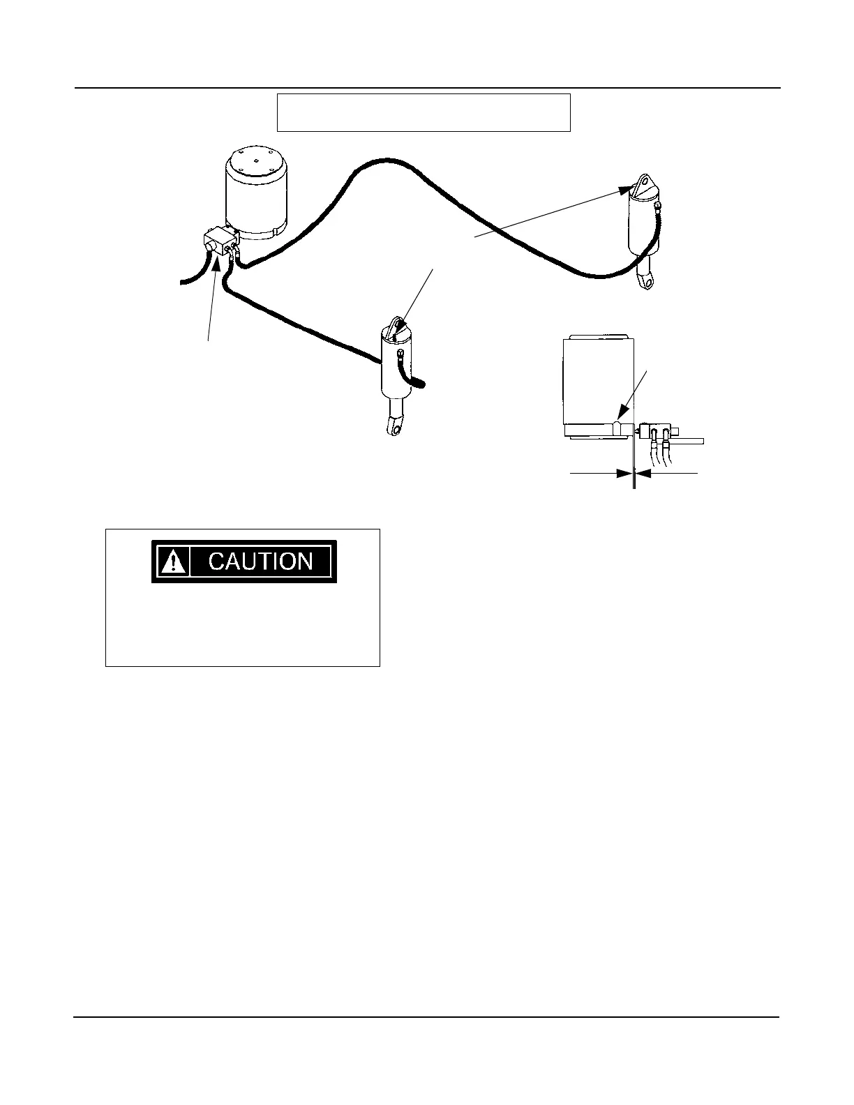
AXLE LOCKOUT SYSTEM
Air in the axle lock circuit decreases sta-
bility. Bleed the system immediately
whenever this occurs.
If the axle does not hold in the blocked position or oscillates
when the upper structure is swung 20 degrees from the travel
position, bleed the system.
Swing the retracted unloaded boom into the travel position so
that the lock valve will open. With the engine running at an
idle, loosen the bleeder screw. When a steady flow of oil is
running from the bleed screw, retighten the bleeder screw.
ADJUSTMENT
With the cam plunger fully retracted, adjust valve position for
.005-.010 inches gap between the cam roller and the cam trav-
el area on the manifold. Do not measure at the low point on
the manifold.
Tighten and secure with nuts, washers, and capscrews.
OPERATION CHECK
For safe operation of the crane when operating on rubber, the
AXLE LOCKOUT SYSTEM
LOW POINT ON
MANIFOLD
.005 / .010
AXLE LOCKOUT
VALVE
BLEED
SCREWS
Issued: August 2003RT700 Series