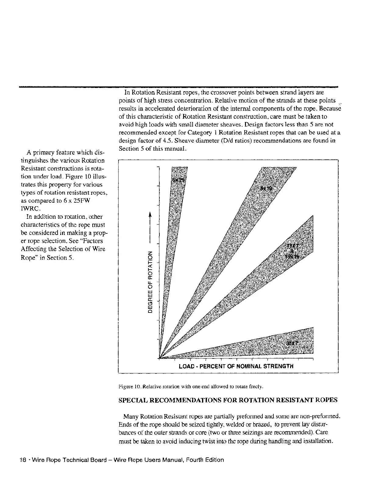
A primary feature which dis-
tinguishes the various Rotation
Resistant constructions is rota-
tion under load. Figure
10
illus-
trates this property for various
types
of
rotation resistant ropes,
as compared to 6 x 25FW
IWRC.
In
addition to rotation, other
characteristics
of
the rope must
be
considered in making a prop-
er
rope selection. See "Factors
Affecting the Selection
of
Wire
Rope" in Section 5.
In Rotation Resistant ropes, the crossover points between strand layers are
points
of
high stress concentration. Relative motion
of
the strands at these points
results in accelerated deterioration
of
the internal components
of
the rope. Because
of
this characteristic
of
Rotation Resistant construction, care must be taken to
avoid high loads with small diameter sheaves. Design factors less than 5 are not
recommended except for Category 1 Rotation Resistant ropes that can be used at a
design factor
of
4.5. Sheave diameter (Did ratios) recommendations are found in
Section 5
of
this manual.
z
o
~
5
a:
I.L.
o
UJ
UJ
a:
Cl
UJ
o
LOAD·
PERCENT OF NOMINAL STRENGTH
Figure 10. Relative rotation with one end allowed to rotate freely.
SPECIAL RECOMMENDATIONS FOR ROTATION RESISTANT ROPES
Many Rotation Resistant ropes are partially preformed and some are non-preformed.
Ends
of
the rope should
be
seized tightly, welded
or
brazed, to prevent
lay
distur-
bances
of
the outer strands
or
core (two or three seizings are recommended). Care
must
be
taken to avoid inducing twist into the rope during handling and installation.
18 • Wire Rope Technical Board - Wire Rope Users Manual, Fourth Edition