Appendix E
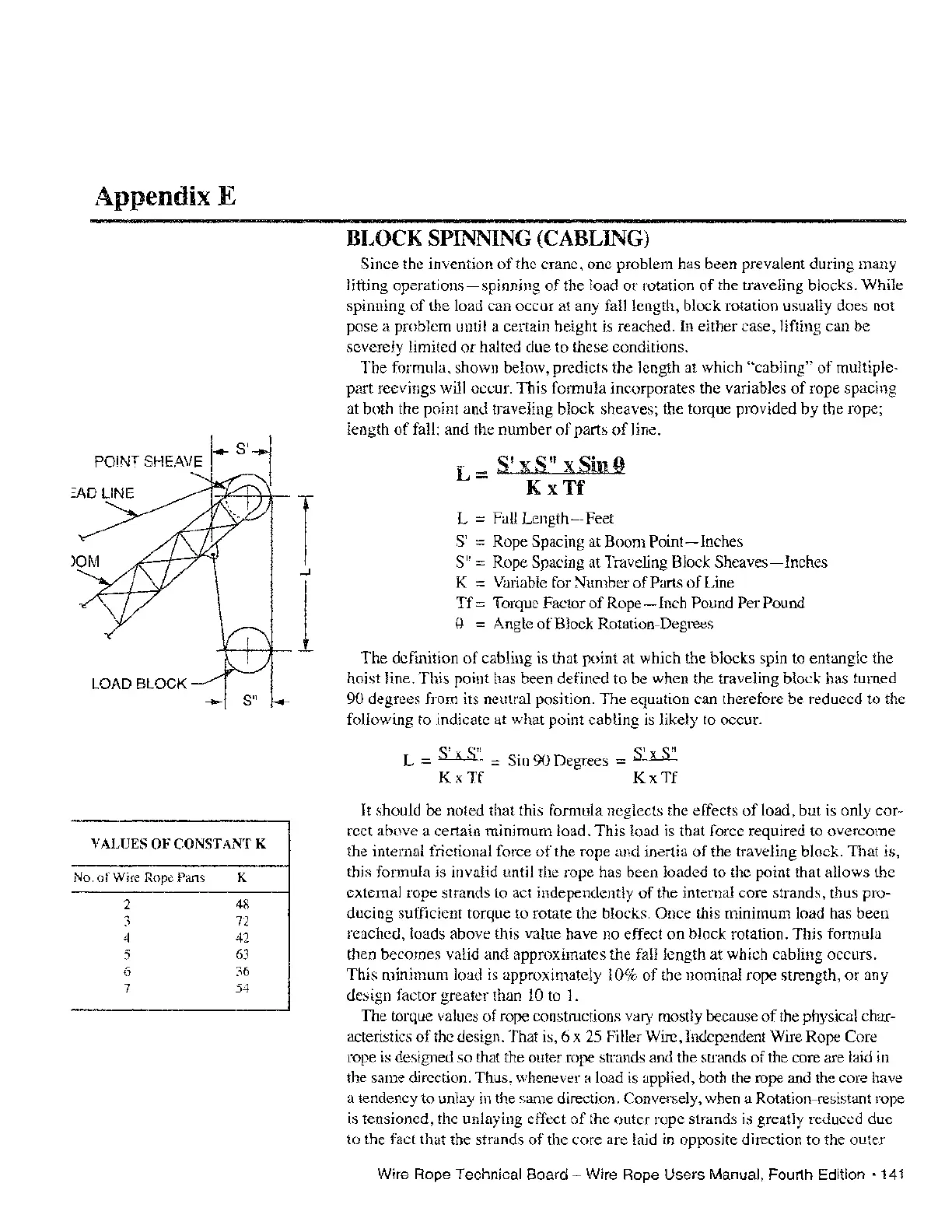
POINT SHEAVE
LOAD BLOCK
VALVES
OF
CONSTANT K
No.
of
Wire Rope Parts K
2
48
3 72
4
42
5
63
6 36
7 54
BLOCK
SPINNING (CABLING)
Since the invention
of
the crane, one problem has been prevalent during many
lifting
operations-spinning
of
the load
or
rotation
of
the traveling blocks. While
spinning
of
the load can occur at any fall length, block rotation usually does not
pose a problem until a certain height
is reached.
In
either case, lifting can be
severely limited
or
halted due to these conditions.
The formula, shown below, predicts the length at which
"cabling"
of
multiple-
part reevings will occur. This formula incorporates the variables
of
rope spacing
at both the point and traveling block sheaves; the torque provided by the rope;
length
of
fall; and the number
of
parts
of
line.
_
SiX
S
II
X Sin Q
-
KxTf
L
==
Fall Length - Feet
S'
==
Rope Spacing at Boom
Point-Inches
S"
==
Rope Spacing at Traveling Block
Sheaves-Inches
K
==
Variable for Number
of
Pmts
of
Line
Tf::::
Torque Factor
of
Rope - Inch Pound Per Pound
Q.
==
Angle
of
Block Rotation-Degrees
The definition
of
cabling is that point at which the blocks spin to entangle the
hoist
line. This point has been defined to be when the traveling block has turned
90 degrees from its neutral position. The equation can therefore be reduced to the
following to indicate at what point cabling
is likely to occur.
S'
S"
S'
~
QII
L
==
_X_
==
Sin 90 Degrees
::::
b!....1LL
KxTf KxTf
It should be noted that this formula neglects the effects
of
load, but is only cor-
rect above a certain minimum load. This load is that force required to overcome
the internal frictional force
of
the rope and inertia
of
the traveling block. That is,
this formula is invalid until the rope has been loaded to the point that allows the
external rope strands to act independently
of
the internal core strands, thus pro-
ducing sufficient torque to rotate the blocks. Once this minimum load has been
reached, loads above this value have no effect on block rotation. This formula
then becomes
valid and approximates the fall length at which cabling occurs.
This minimum load is approximately 10%
of
the nominal rope strength,
or
any
design factor greater than
10
to
1.
The torque values
of
rope constructions vary mostly because
of
the physical char-
acteristics
of
the design. That is, 6 x
25
Filler Wire, Independent Wire Rope Core
rope
is
designed so that the outer rope strands and the strands
of
the core
m'e
laid in
the same direction. Thus, whenever a load is applied, both the rope andthe core have
a tendency to unlay
in the same direction. Conversely, when a Rotation-resistant rope
is tensioned, the unlaying effect
of
the outer rope strands is greatly reduced due
to the fact that the strands
of
the core are laid in opposite direction to the outer
Wire Rope Technical Board - Wire Rope Users Manual, Fourth Edition
'141