CC1101
SWRS061H Page 80 of 98
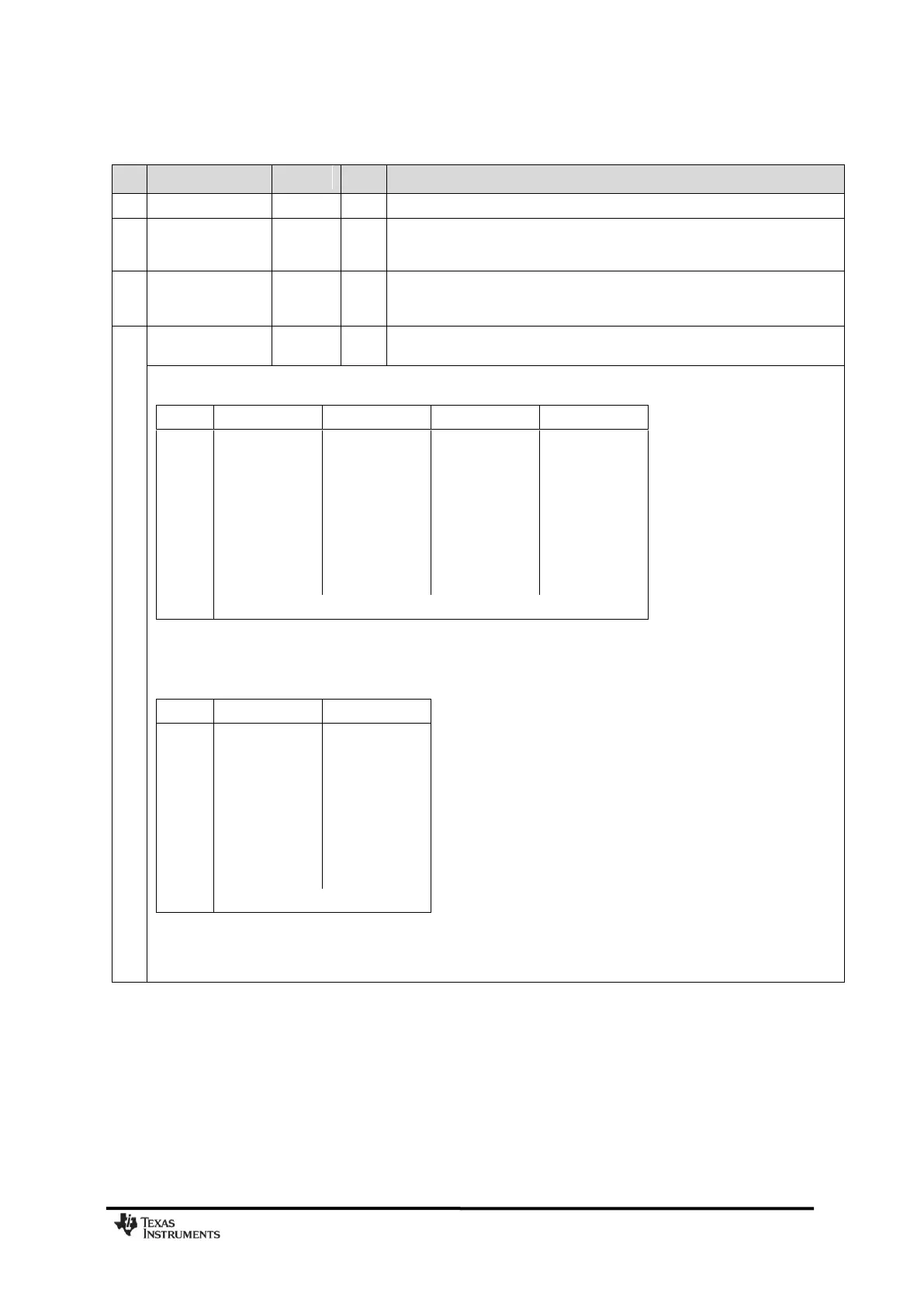
0x16: MCSM2 – Main Radio Control State Machine Configuration
Direct RX termination based on RSSI measurement (carrier sense). For
ASK/OOK modulation, RX times out if there is no carrier sense in the first 8
symbol periods.
When the RX_TIME timer expires, the chip checks if sync word is found when
RX_TIME_QUAL=0, or either sync word is found or PQI is set when
RX_TIME_QUAL=1.
Timeout for sync word search in RX for both WOR mode and normal RX
operation. The timeout is relative to the programmed EVENT0 timeout.
The RX timeout in µs is given by EVENT0·C(RX_TIME, WOR_RES) ·26/X, where C is given by the table below and X is the
crystal oscillator frequency in MHz:
As an example, EVENT0=34666, WOR_RES=0 and RX_TIME=6 corresponds to 1.96 ms RX timeout, 1 s polling interval and
0.195% duty cycle. Note that WOR_RES should be 0 or 1 when using WOR because using WOR_RES > 1 will give a very low
duty cycle. In applications where WOR is not used all settings of WOR_RES can be used.
The duty cycle using WOR is approximated by:
Note that the RC oscillator must be enabled in order to use setting 0-6, because the timeout counts RC oscillator periods.
WOR mode does not need to be enabled.
The timeout counter resolution is limited: With RX_TIME=0, the timeout count is given by the 13 MSBs of EVENT0,
decreasing to the 7MSBs of EVENT0 with RX_TIME=6.