CC1101
SWRS061H Page 84 of 98
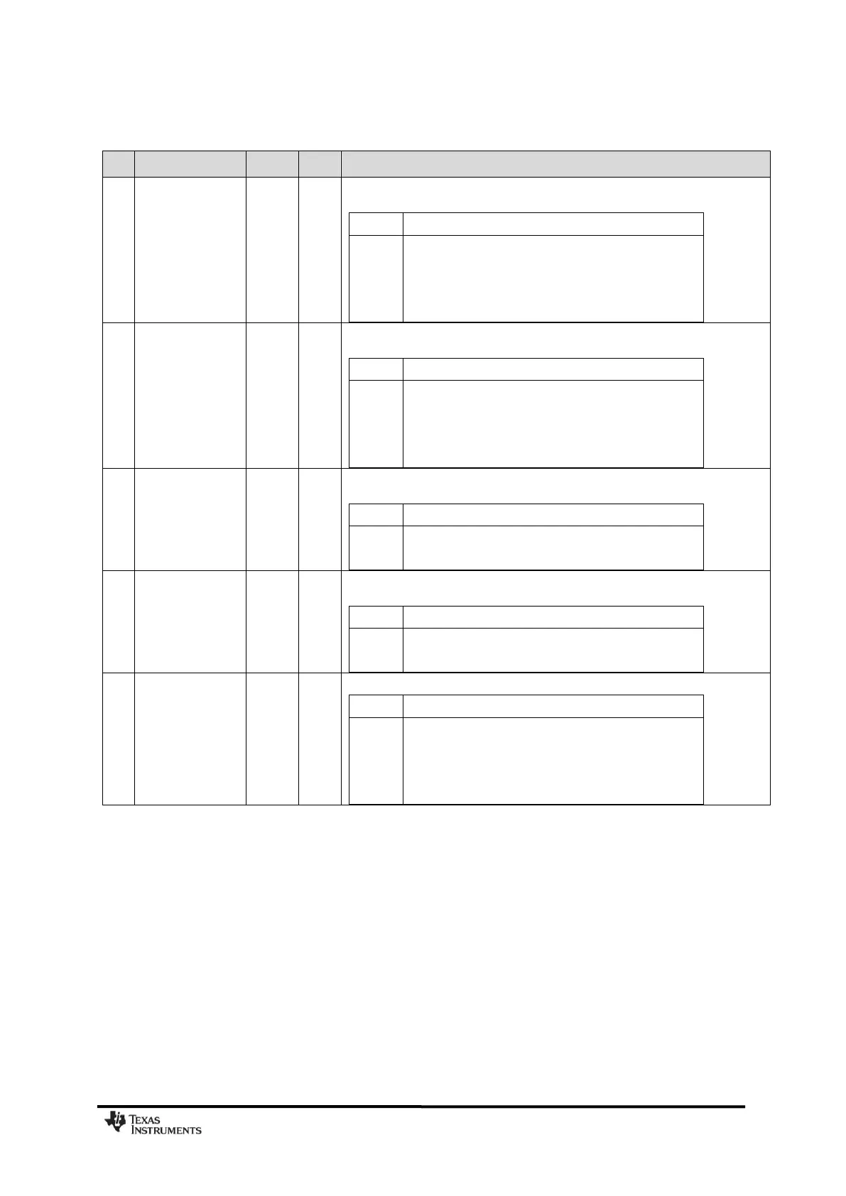
0x1A: BSCFG – Bit Synchronization Configuration
The clock recovery feedback loop integral gain to be used before a sync word is
detected (used to correct offsets in data rate):
Clock recovery loop integral gain before sync word
The clock recovery feedback loop proportional gain to be used before a sync word
is detected.
Clock recovery loop proportional gain before sync word
The clock recovery feedback loop integral gain to be used after a sync word is
detected.
Clock recovery loop integral gain after sync word
The clock recovery feedback loop proportional gain to be used after a sync word
is detected.
Clock recovery loop proportional gain after sync word
The saturation point for the data rate offset compensation algorithm:
Data rate offset saturation (max data rate difference)
±0 (No data rate offset compensation performed)
±3.125 % data rate offset