CC1101
SWRS061H Page 85 of 98
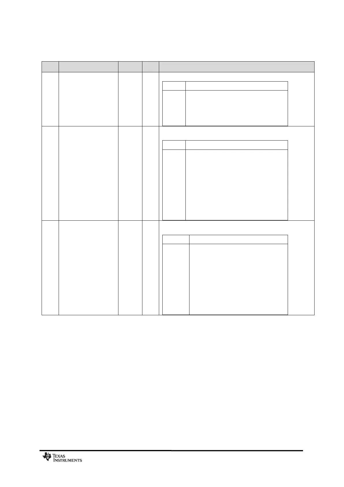
0x1B: AGCCTRL2 – AGC Control
Reduces the maximum allowable DVGA gain.
All gain settings can be used
The highest gain setting can not be used
The 2 highest gain settings can not be used
The 3 highest gain settings can not be used
Sets the maximum allowable LNA + LNA 2 gain relative to the maximum
possible gain.
Maximum allowable LNA + LNA 2 gain
Maximum possible LNA + LNA 2 gain
Approx. 2.6 dB below maximum possible gain
Approx. 6.1 dB below maximum possible gain
Approx. 7.4 dB below maximum possible gain
Approx. 9.2 dB below maximum possible gain
Approx. 11.5 dB below maximum possible gain
Approx. 14.6 dB below maximum possible gain
Approx. 17.1 dB below maximum possible gain
These bits set the target value for the averaged amplitude from the
digital channel filter (1 LSB = 0 dB).
Target amplitude from channel filter