• Programmable hysteresis
• Programmable reference voltage:
– External reference voltage (VREF IO)
– Internal reference voltage (1.4V, 2.5V)
– Integrated 8-bit reference DAC, the output can also connect to OPA input terminal internally as an output
buffer.
• Configurable operation modes:
– High speed mode
– Lower power mode
• Programmable output glitch filter delay
• Supports 6 blanking sources . Please refer to CTL2 register in comparator section of TRM
• Support output wake up device from all low power modes
• Output connected to advanced timer fault handling mechanism
• The IPSEL and IMSEL bits in comparator registers can be used to select the comparator channel inputs from
device pins or from internal analog modules.
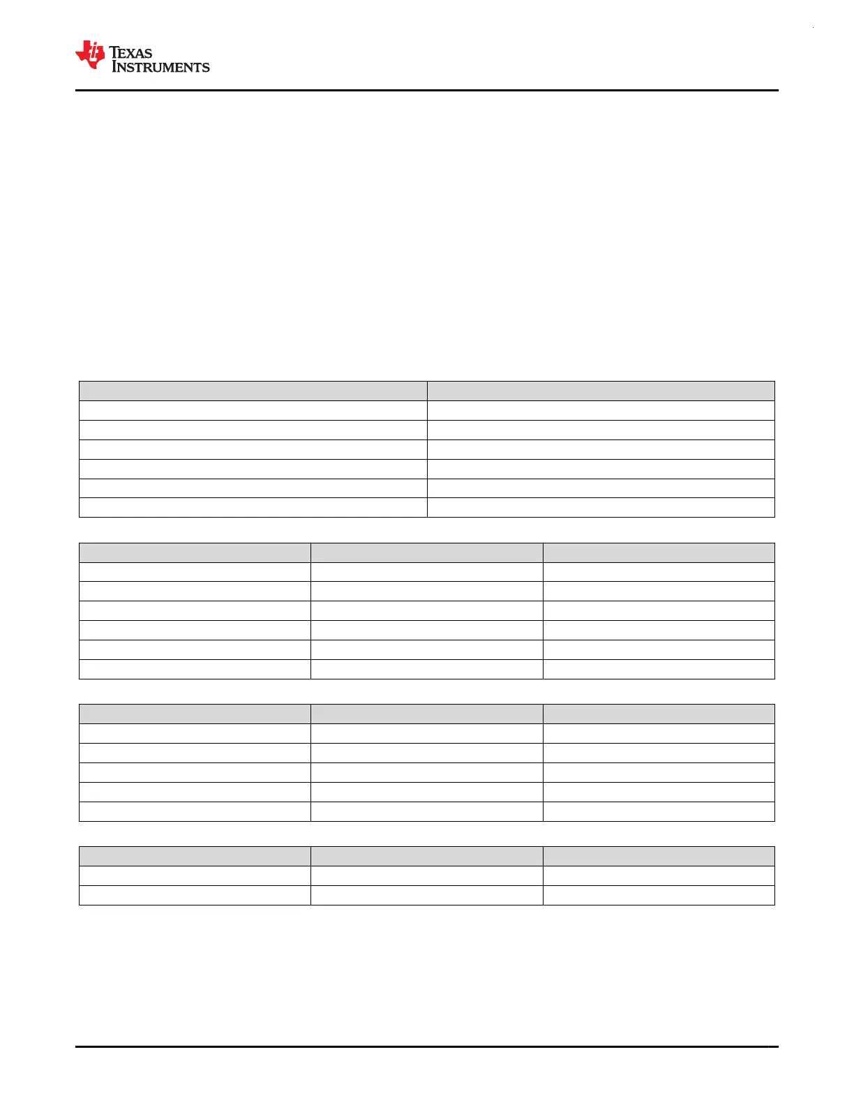
Table 8-8. COMP Blanking Source Table
CTL2.BLANKSRC VALUE BLANKING SOURCE
1 TIMA0.CC2
2 TIMA0.CC3
3 TIMA1.CC1
4 TIMG12.CC1
5 TIMG6.CC1
6 TIMG7.CC1
Table 8-9. COMP0 Input Channel Selection
IPSEL / IMSEL BITS POSITIVE TERMINAL INPUT NEGATIVE TERMINAL INPUT
0x0 COMP0_IN0+ COMP0_IN0-
0x1 COMP0_IN1+ COMP0_IN1-
0x2 COMP0_IN2+ COMP0_IN2-
0x5 DAC_OUT / COMP0_IN3+
(1)
-
0x6 OPA1 output OPA0 output
0x7 COMP1 positive terminal signal -
Table 8-10. COMP1 Input Channel Selection
IPSEL / IMSEL BITS POSITIVE TERMINAL INPUT NEGATIVE TERMINAL INPUT
0x0 COMP1_IN0+ COMP1_IN0-
0x1 COMP1_IN1+ COMP1_IN1-
0x2 COMP1_IN2+ COMP1_IN2-
0x5 DAC_OUT / COMP1_IN3+
(1)
-
0x7 COMP0 positive terminal signal -
Table 8-11. COMP2 Input Channel Selection
IPSEL / IMSEL BITS POSITIVE TERMINAL INPUT NEGATIVE TERMINAL INPUT
0x0 COMP2_IN0+ COMP2_IN0-
0x1 COMP2_IN1+ COMP2_IN1-
(1) The connection to COMP0/1_IN3+ and DAC_OUT connects using the PA15 pin. When connecting DAC_OUT to COMP0/1_IN3+,
avoid using external circuitry on the PA15 pin.
For more information about device analog connections, see Section 8.30.
For more details, see the COMP chapter of the MSPM0 G-Series 80-MHz Microcontrollers Technical Reference
Manual.
www.ti.com
MSPM0G3507, MSPM0G3506, MSPM0G3505
SLASEX6A – FEBRUARY 2023 – REVISED JUNE 2023
Copyright © 2023 Texas Instruments Incorporated
Submit Document Feedback
63
Product Folder Links: MSPM0G3507 MSPM0G3506 MSPM0G3505
 Loading...


