16V
1uF
C65
16V
1uF
C68
GND
OUT
1
GND
2
PAD
5
EN
3
IN
4
TLV75533PDQNT
U11
GND
GND
AGND
13
AGND
14
AGND
15
BIAS
9
CBOOT
6
EN
18
FB
12
NC
7
NC
19
NC
23
NC
27
NC
28
NC
29
NC
30
PAD
31
P GND
26
P GND
24
P GND
25
P GO OD
16
P VIN
20
P VIN
21
P VIN
22
RT
10
S S /TRK
11
S W
5
S W
1
S W
2
S W
3
S W
4
SYNC/MODE
17
VCC
8
LM76005RNPR
U10
4.7uH
L3
10V
0.47uF
C69
100k
R98
23.7k
R100
16V
220uF
C70
470nF
50V
C71
100V
0.47uF
C67
100V
4.7uF
C66
16V
2.2uF
C64
GND GND
GND
GND
GND
GND GND
GND
PP5V
P3V3
VSYS
PP5V
GND
100k
R99
100V
15pF
C72
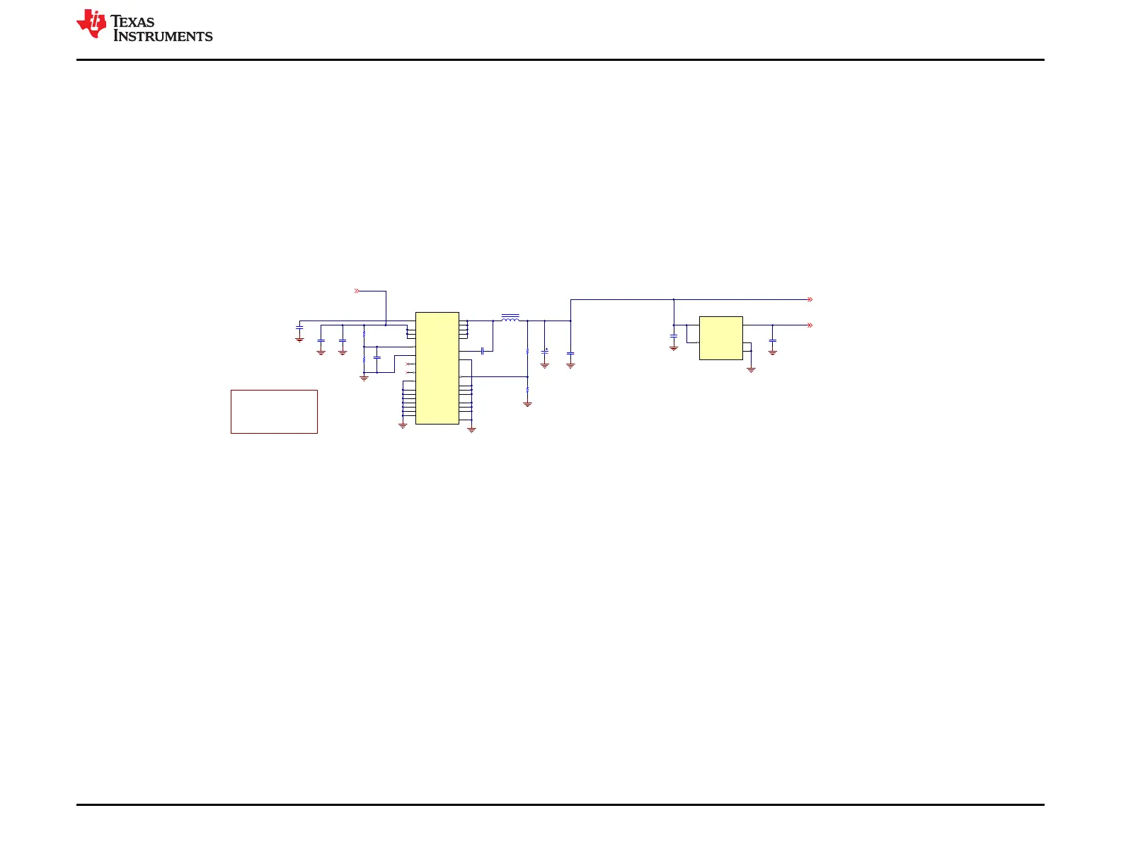
Enable Voltage Range
P lea se no te :
In orde r for de vice p owe rs ta ge to work, a
minimum of 7.5V and m a xim u m o f 42V is
ne e ded to e nab le bu ck co nve rte r (LM76005 ).
This is s cale d to s upport 2S -10S ba tte ry.
If you wish to a llow for lower inp ut volta ge ,
you will ne ed to c han ge en a ble p in UVLO
co ndition with R 115 and R11 6.
Figure 5-3. Power Stage Schematic
www.ti.com Hardware Design Files
SLVUCP9A – NOVEMBER 2023 – REVISED MARCH 2024
Submit Document Feedback
TPS25751 Evaluation Module 35
Copyright © 2024 Texas Instruments Incorporated