NBC™ Flat Belt - IOM
P/N: 1118140 Rev: 07/29/2020 Page 80 of 129
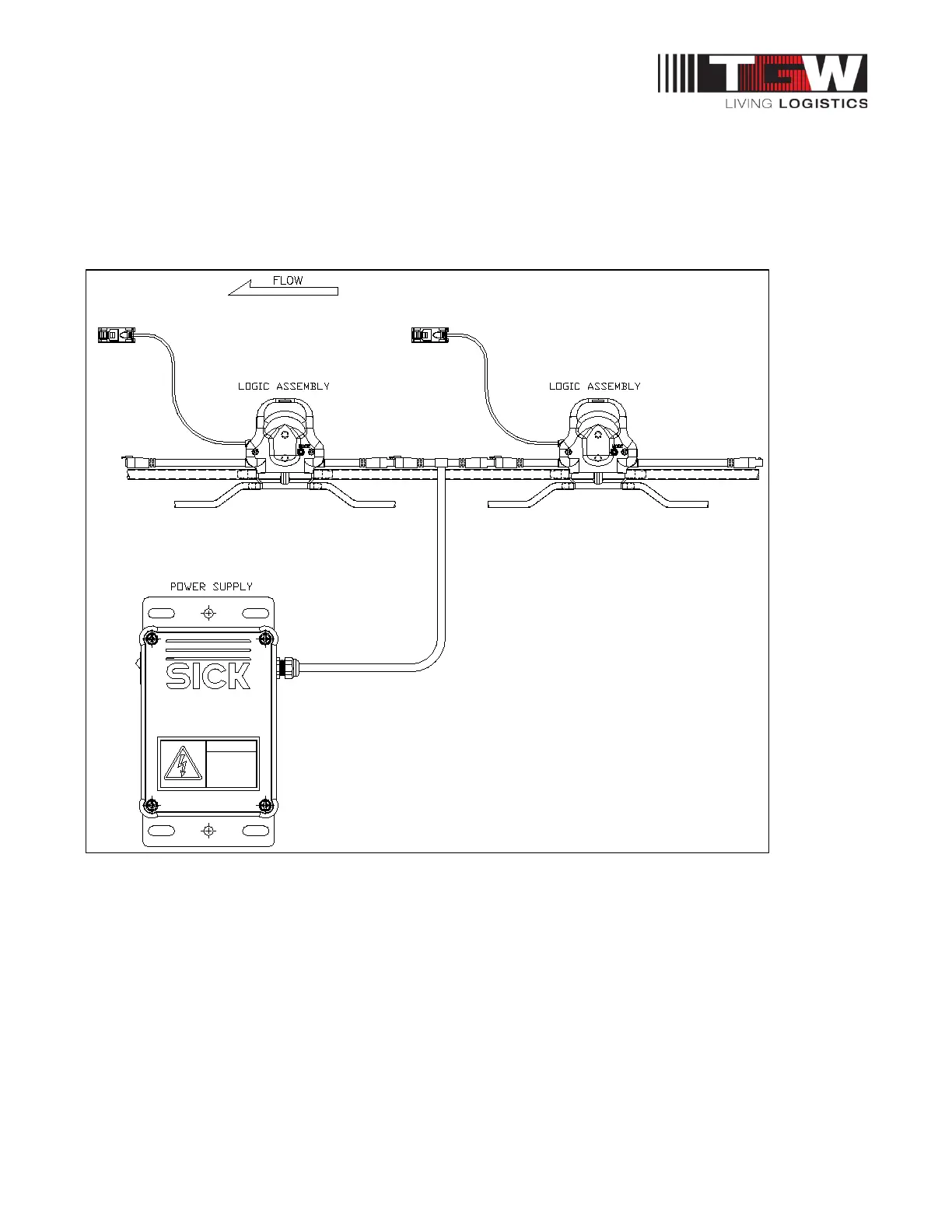
1.42: POWER SUPPLY WIRING
Connection made between two Logic Assemblies using a T Cable
This drawing illustrates a power connection made between two intermediate accumulation zones
making use of a “T” Cable. NOTE that all power and control signals, including the Slug and Logic
Signals, pass through the “T” Cable uninterrupted.
Figure 8: Two Logic Assemblies using a T Cable
A “T” cable must be installed between two logic module assemblies. Preferably located in the middle
of the logic modules connected to the power supply.