NBC™ Flat Belt - IOM
P/N: 1118140 Rev: 07/29/2020 Page 98 of 129
Pneumatic Valve
The pneumatic valve shall be embedded in the logic module housing and satisfy the requirements
outlined in Table 20.
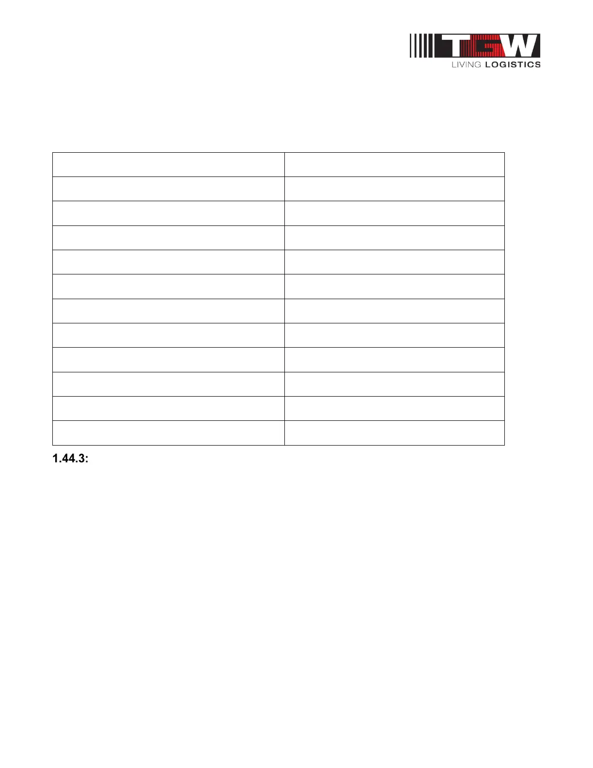
Table 17: Pneumatic Valve Specification
Operating Pressure Range 0-40 PSI (0-2.75 bar)
Flowrate Capacity ≥ 0.04 Cv (40 Nl/m)
Ventilation Capacity ≥ 0.04 Cv (40 Nl/m)
Power Consumption 1W
Minimum Supply Voltage 19.2 VDC
Maximum Supply Voltage 27.6 VDC
Duty Cycle 100%
Life Expectancy 100 million cycles
Input Air Connection 3/8 in. (9.5mm) barbed fitting
Output Air Connection 1/4 in. (6mm) barbed fitting
Operating Mode N.O. (Air to Brake)
Air supply Non-lubricated, 5 micron or less
Sensor/Valve Assembly
The Sensor/Valve Assembly module differs from the standard module in that it does not have a
female cable connection, does not connect to a neighboring module, does not contain logic, and has a
unique wiring scheme on the male connection. This module may be simply described as a junction
box with connection to provide +VDC to the sensor and valve, sensor output to the PLC, and valve
input from the PLC. The male connection interface will be a cable with flying leads and have two
meter (2m) length. The jacket shall be stripped and conductors perforated. See the current
Sensor/Valve Assembly, E0006229, for reference.