MEC 310 GENSET CONTROLLER
PM075 REV 2 09/08/20 Page 33 THOMSON TECHNOLOGY
Configuration of the digital alarm inputs
The digital inputs are configured via the utility software (USW).
Remember to save and write the settings to the unit.
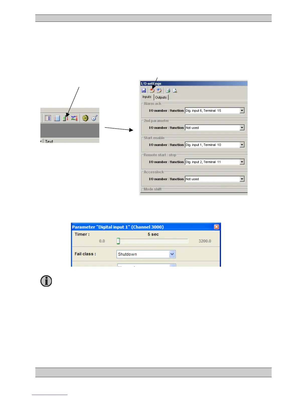
Use this button to upload the menu.
The individual I/O number and the function
are now selected. In the example below
‘
Digital input 1
’ is chosen, and a terminal
number must be assigned to the input. If the
input is used as alarm input, then the name
can be changed to the relevant name
selected from the predefined list below.
3000-3050 Digital input term. 10-15, without wire break detection
Complete the input settings and select the appropriate fail class and outputs. The outputs A and B
can be used to activate one or two of the configurable relay outputs or LEDs. If the relay function is
set as a limit relay, no warning pop-up will be shown in the display. The relay 0 is a virtual relay, so
both output A and B must be set to limit relays if no warning in the display is wanted.
Renaming of the Digital input can be done in Translation.