© 2016 Thorlabs Scientific Imaging
5 Specifications
471
5.5 Camera Interface
This section of the manual contains information on connecting the cameras and wiring IOs.
For information on a camera's power consumption, please refer to the Camera and sensor data
section. This section contains information on all camera models sorted by sensor type.
DCU223x, DCU224x, DCC1240x
DCC3240x
EEPROM Specification
5.5.1 DCU223x, DCU224x, DCC1240x
In this section the additional digital input / output of these cameras is described in detail:
I/O Connector - Pin Assignment
Digital Input (Trigger) Circuit
Digital Output (Flash) Circuit
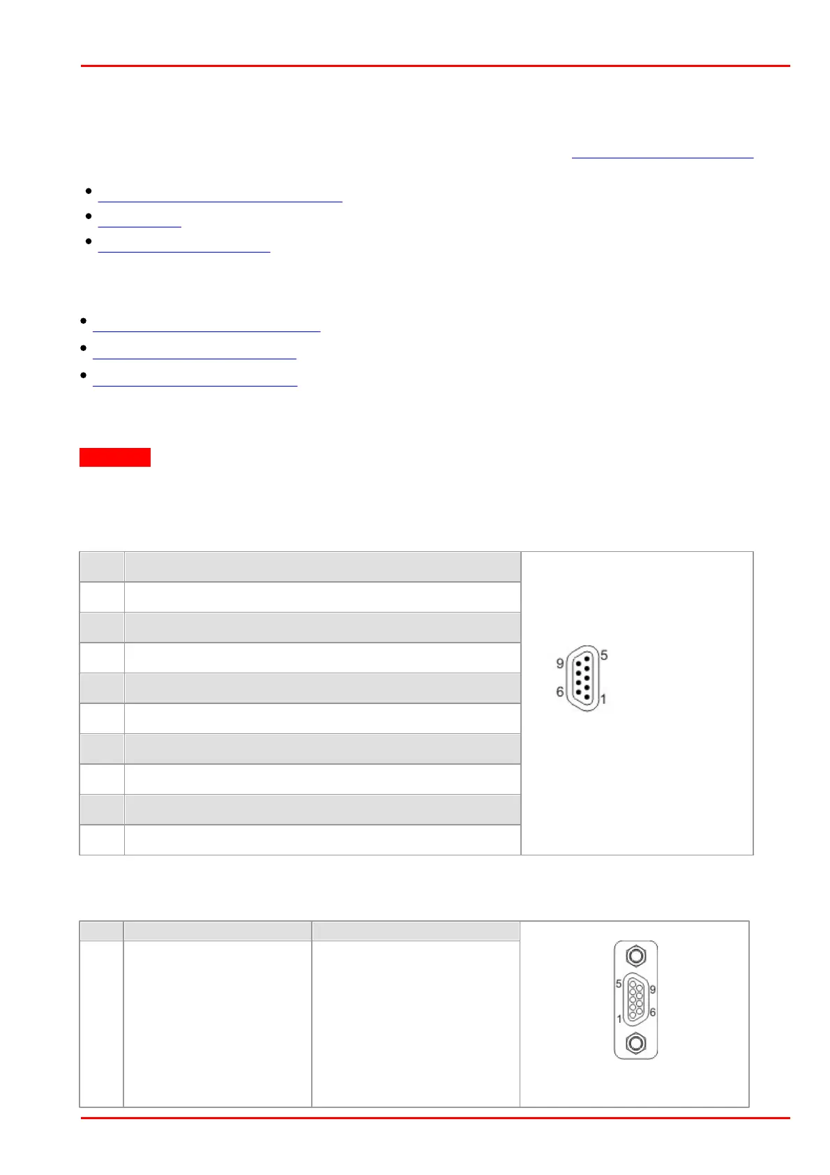
5.5.1.1 I/O Connector - Pin Assignment
Attention
USB cables with non-standard connectors must be connected to the camera first and then to the
PC. Otherwise the camera might not be recognized correctly.
9-pin micro D-Sub socket
DCU22xX / DCC1240X
Micro D-Sub socket male,
camera rear view
USB power supply (VCC) 5 V
Pin assignment of the CAB-DCU-Tx cable for USB 2.0, trigger and flash
 Loading...