© 2013 Thorlabs GmbH
5 Specifications
489
5.5.1.3 Digital Output (Flash) Circuit
Digital output specifications
Output current (short-time)
Output current (permanent)
Collector power dissipation
NOTE
*) For information on how to determine the USB board revision, please refer to the DCx Driver Compatibility
chapter.
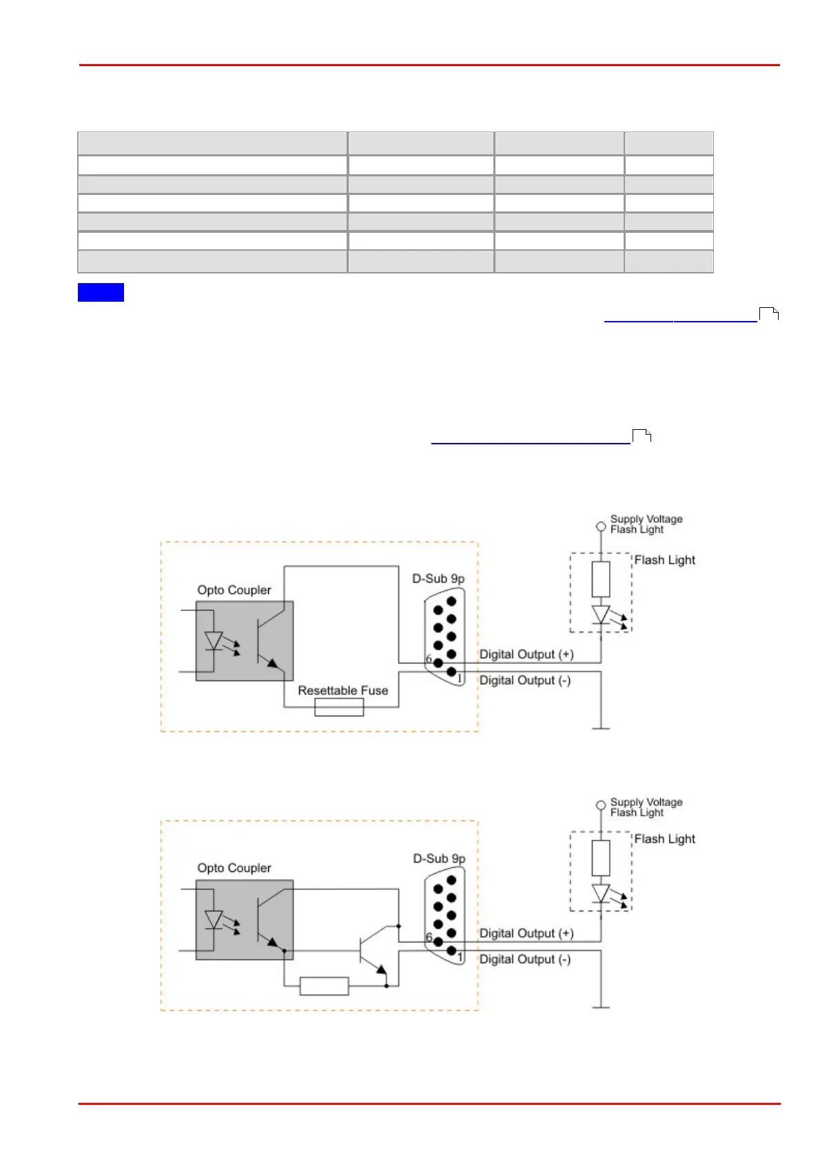
The digital output is galvanically isolated using an opto coupler to protect the camera and the PC against surges.
Only DC voltages may be applied to the digital input.
The output of the opto coupler can be used as an open collector or open emitter output. This means that the output
signal can be connected to ground or to the supply voltage. The output signal is active if the collector-emitter switch
is closed (software setting: Flash high active, see also the Camera Properties: Input/Output section).
Digital output wiring
The following figures show examples of how the digital output is wired.
Wiring of the digital output as an open collector output (rev. 1.2)
Wiring of the digital output as an open collector output (rev. 2.0)
58
104
 Loading...