EasyManuals Logo

THORLABS DCU223 SERIES User Manual

THORLABS DCU223 SERIES
530 pages
To Next Page IconTo Next Page
To Previous Page IconTo Previous Page
Page #495 background imageLoading...
Page #495 background image
© 2013 Thorlabs GmbH
5 Specifications
493
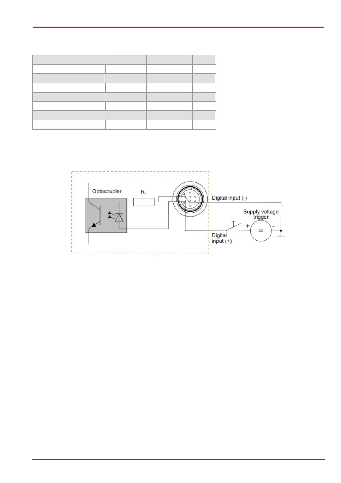
5.5.2.3 Digital Input (Trigger) Circuit
Digital input specifications
Min.
Max.
Level low
0
1
V
Level high
5
24
V
Voltage range
0
-
V
Trigger pulse width (edge)
10
-
µs
Trigger edge steepness
35
-
V/ms
Breakdown voltage
-
50
V
Input current
10
-
mA
For interpreting the trigger signal, either the negative or the falling edge can be used. The digital input is
galvanically isolated using an optocoupler to protect the camera and the PC against surges. Only DC voltages may
be applied to the digital input.
Digital input wiring
Wiring of the trigger connector

Table of Contents

Other manuals for THORLABS DCU223 SERIES

Questions and Answers:

Question and Answer IconNeed help?

Do you have a question about the THORLABS DCU223 SERIES and is the answer not in the manual?

THORLABS DCU223 SERIES Specifications

General IconGeneral
BrandTHORLABS
ModelDCU223 SERIES
CategorySecurity Camera
LanguageEnglish

Related product manuals