252
NVA100X-D - Manual - 02 - 2016
FUNCTION CHARACTERISTICS
To enable the selectivity logic input for a generic xx element, the xxBLK2IN parameters mu be set
to ON inside the Set \ Parametri di confi gurazione A (o B) \ xxx \ Setpoints menus concerning all
element where the selective block is available, eg:
I>BLK2IN inside the Set \ Profi le A(or B) \ Phase overcurrent-50/51 \ I> Element \ Setpoints menu.
Output selective block
Use of output relays
If the xxBLK2OUT, xxBLK2OUT and/or xxBLK2OUT enable parameters are set to ON and a
output relay is designed for selective block (Block2), the protection issues a block output by phase
elements (BLK2OUT-Iph), by ground elements (BLK2OUT-IE) or by any protection element (BLK2OUT-
Iph/IE), whenever the given start is active.
The BLK2OUT-Iph-K, BLK2OUT-Iph/IE-K and/or BLK2OUT-IE-K output relays must be set in-
side the Set \ Profi le A(or B) \ Selective block-BLOCK2 \ Selective block OUT menu; the same for ad-
dressing the LED indicators (BLK2OUT2-Iph-L, BLK2OUT2-IE-L and BLK2OUT2-Iph/IE_L).
When output relays are programmed for selective block output, the t
TR
time delays must reset to
zero; the operation mode must be set with self reset (No-latched inside Set \ Relays submenu) and
the Logic parameters (Energized/De-energized) must be programmed in the same way of the
related binary input connected with-it.
Use of committed pilot wire output BLOUT1
The output is a dry static relay.
The information about phase (ON IPh), earth (ON IE), or phase+earth (ON IPh/IE) concerning the
sending block out signal may be select by means of the ModeBLOUT1 parameter inside the Set \
Profi le A(or B) \ Selective block-BLOCK2 \ Selective block OUT menu.
The parameters can be set separately for A and B profi les.
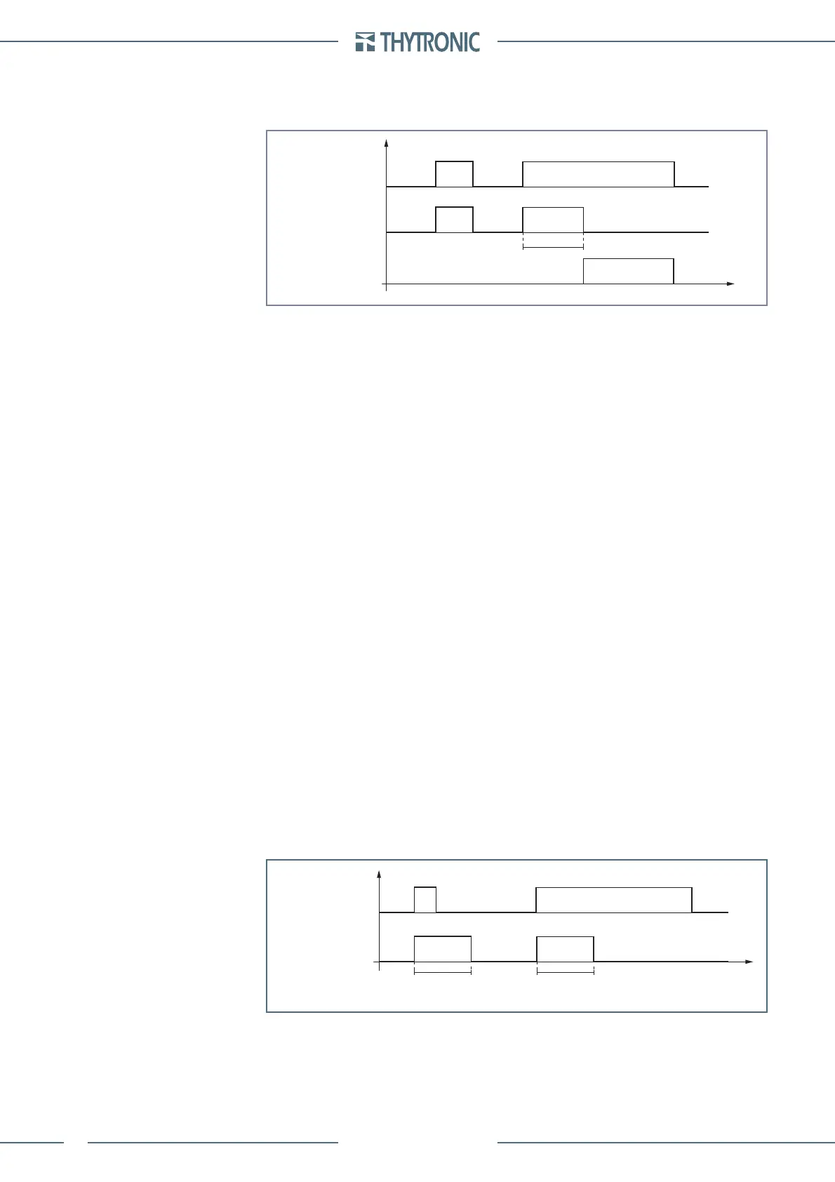
Operation
The selective block outputs go ON at the same time of the xx element start; they hold steady (even
if the start reset to zero) for along the t
F-IPh
, t
F-IE
and
t
F-IPh/IE
adjustable times for phase, earth and
phase+earth functions.
The timers starts when one or more selective block function goes ON; when a timer expires, the
selective block outputs are disregarded (even if the start holds steady).
The t
F-IPh
and t
F-IE
counters start when the output selective block becomes active. When the coun-
ters expire the block selective output is forced off (despite the start xxx remain active).
If the t
F-IPh
, t
F-IE
e
t
F-IPh/IE
timers are cleared the selective block output state is freeze up to the start
xxx remain active.
With a setting other than 0.00 s, the t
F-IPh
, t
F-IE
e
t
F-IPh/IE
timers may be used to provide a backup
protection against breaker failure inside a selectivity logic system, as well as to hold blocked up-
stream protective relays up after the fault is cleared with CB opening to provide solution against
unwanted trips because of a larger reset time compared with the downstream relay (the selectivity
will be lost).
With traditional selective logic systems, in the absence of suitable cares, the event of a circuit
breaker failure causes the block of the receiving relays situated upstream the circuit breaker, so the
fault cannot be cleared.
TB-timer.ai
t
t
B-Iph
/t
B-IE
BLIN2IN-Iph/BLIN2IN-IE
tB timeout
INPUT BLOCK
(binary input and/or BLIN1)
tB timer
TF-timer.ai
t
t
F-IPh,
t
F-IE,
t
F-IPh/IE
t
F-IPh,
t
F-IE,
t
F-IPh/IE
Start xx
(protezioni interne)
tF timer (Block2)
BLK2OUT-Iph
BLK2OUT-IE
BLK2OUT-Iph/IE
 Loading...


