44
■ Proportional band setting for OUT2
Character
Name
Description
Initial Value
1
SET3
CNT
Setting Mode Selection
Screen
Control Parameter Mode
Settings about Control
27
P2
Proportional band
setting for OUT2
Setting Range: 0.10–10.00
Setting Unit: Magnification for Output 1 proportional band
100
Sets the proportional band for Output 2.
Proportional band of Output 2 shall be set with the magnification ratio of x0.1–x10 against the proportional band of Output
1.
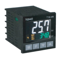
Proportional band of Output 2 will always be set to the opposite side of SV from the proportional band of Output 1.
[Sample Setting]
If the proportional band of Output 2 (P2) is set to 2.00, then the proportional band of P2 becomes two times larger than the
proportional band of Output 1 (P1).
■ Proportional cycle setting for OUT2
Character
Name
Description
Initial Value
1
SET3
CNT
Setting Mode Selection
Screen
Control Parameter Mode
Settings about Control
28
T2
Proportional cycle
setting for OUT2
Setting Range: 1–120
Setting Unit: Second
20
Sets the proportional cycle of output 2.
Since the output of relay contact point and voltage for SSR drive only have a state of either ON or OFF, proportional
operation cannot be performed. To make the proportional operation work in such a state, the concept is called “Time
Proportional Operation.”
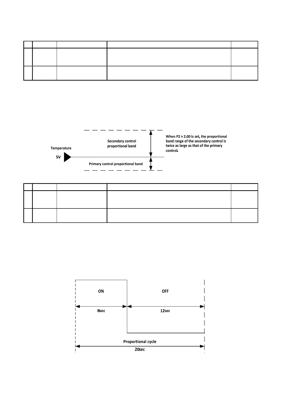
In a time proportional control, the method of turning ON for a fixed period of time and turning OFF for the rest of the time
will be repeated in accordance with the designated proportional cycle (time cycle).
Example: If proportional cycle is 20 seconds and manipulated variable (MV) is 40%