ISOCAN / ISOBUS ARTEMIS - SEED DRILL CONTROLLER
18
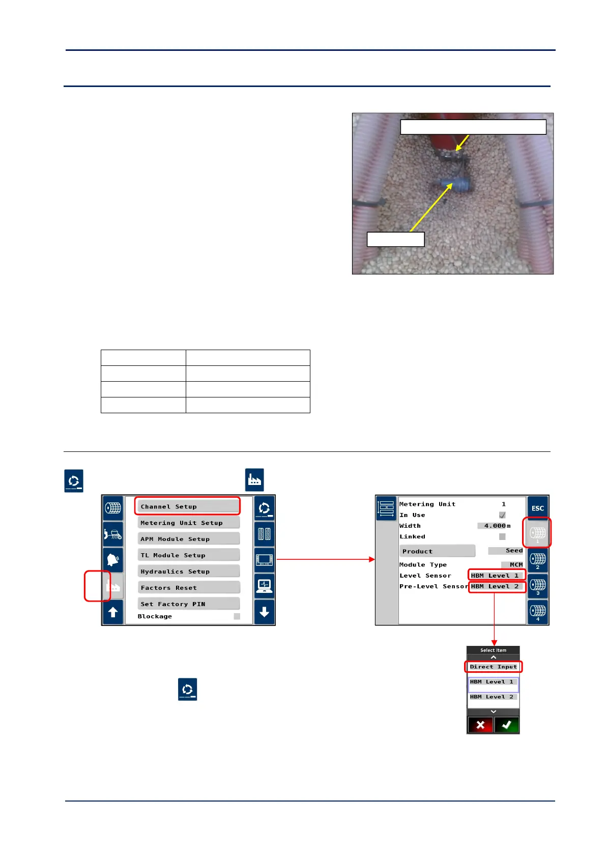
3.8 Hopper Level sensors
Depending on the drill configuration, for each channel in use there can be either,
(i) a single low-level sensor (sensor ‘1’).
(ii) Both a low-level sensor and an upper “Pre-Level” level sensor
(sensor ‘2’). The additional “pre-level” sensor is positioned
higher up in the hopper to provide the operator a more
advanced warning.
Mount the sensor(s) [48] either through the tank wall (requires
a 27mm hole) or inside the tank at the appropriate height(s). If
the sensor is mounted inside the tank, the height can if
necessary, be adjusted e.g. to suit different products.
Route the cable(s) back to connector ‘E’ (for sensor ‘1’) and connector ‘D’ (for sensor ‘2’) of the Expansion Harness
S/TC/1015540-01.
For multi-channel systems where level sensors are installed for each channel (product), all sensors (8 in total for a 4-
channel system), then these are connected to their respective Expansion Harness S/TC/1015540-01 for MCM-2, MCM-3,
and MCM-4.
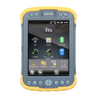
3.8.1 Hopper level sensor configuration
Setup in the Artemis app as follows.
1. Cycle to the ‘Setup’ screen, touch the tab and select “Channel Setup”.
2. Select the channel.
3. Scroll to “Level Sensor” and “Pre-Level Sensor”.
4. For each, set “Direct Input”.
5. Press ESC and then to return to the operating screen.