ISOCAN / ISOBUS ARTEMIS - SEED DRILL CONTROLLER
23
4.4 Tramline Mechanisms
RDS does not supply tramline mechanisms. Only solenoid or motor-type mechanisms fitted with limit switches can be
operated. The tramline outputs operate as follows;
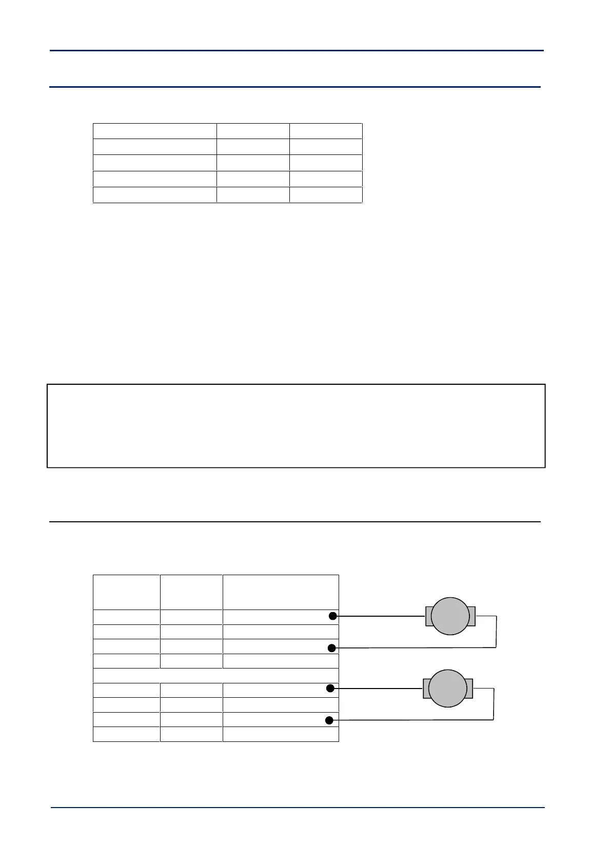
TL1 output only = Assymetric right sequence
TL2 output only = Assymetric left sequence
TL1 + TL2 outputs = Symmetrical sequence
Using the multimeter, first test the tramline mechanisms to determine how they work. There is one of three options:
Motor-driven – power to open / power to close (divertor valve).
Solenoid – Power to open / Spring close.
Solenoid – Spring open / Power to close.
Dependent on the type of tramline mechanisms fitted, then re-connect the existing wiring to the ISOBUS Artemis ECU
connectors labelled ‘TL1’ and ‘TL2’.
Please refer to section 5.2.2 for connection information.
NOTE: Electrical Interference Suppression
When interfacing with solenoids, they must be adequately suppressed to prevent the possibility of electrical interference
damaging the control system. Use a continuity tester between the +V and 0V wires prior to connection to determine if a
diode is already fitted. Solenoid leads have diodes fitted in the solenoid cap and no further action is required. However, if
you are using other means of connection, please refer to the RDS leaflet ref. Pt. No. S/DC/500-10-187 included with the
kit.
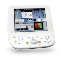
4.4.1 Motor-type Tramline mechanisms
NOTE: The mechanisms must have limit switches.
If the motors operate in the opposite direction to that required, then simply reverse the connections to pins 1 and 3.