ISOCAN / ISOBUS ARTEMIS - SEED DRILL CONTROLLER
19
4 ECU and Sensors
This section details the components that are connected via the Artemis ISOBUS ECU.
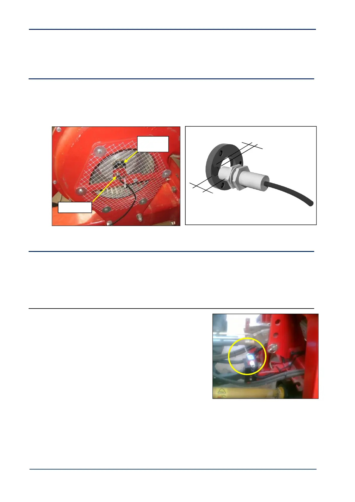
4.1 Fan Speed Sensor
Fit the magnet carrier [51] on the fan shaft. Mount the sensor [49] adjacent to the magnet by suitable means. Note the
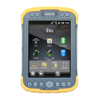
magnet-sensor position as shown in fig. 19.
Route the cable back to the connector labelled ‘FAN 1’ on the ISOBUS Artemis ECU harness. If a 2
nd
fan speed sensor is
required, this goes to the connector labelled ‘FAN 2’.
Figure 18: Typical mounting – Fan Speed Sensor Figure 19: Magnet-Sensor position
4.2 Area Cutout / Lift-Lower / Tramline advance
On ISOBUS installations, the area cutout signal is normally provided from the Topcon retrofitted area cutout switch. A
second ‘drill-lowered’ switch (optional) may be also installed to operate in conjunction with the area-cutout switch to
enable “Lift-Lower” drill operation.
Tramline advance is normally enabled via the area cutout switch.
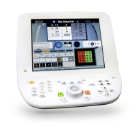
4.2.1 Area cutout / Tramline advance
Part Ref. S/SW/500-7-018
The Area cut-out switch [55] is used to stop/start the motor when
the drill is lifted/lowered. It can also be used for the tramline advance
signal, simplifying the installation.
Mount the switch where it will be triggered as the drill is
lifted/lowered, usually by some part of the 3-point linkage.
Route the cable back to the connector labelled ‘AREA CUTOUT’ on
the ISOBUS Artemis ECU harness.