ISOCAN / ISOBUS ARTEMIS - SEED DRILL CONTROLLER
20
4.2.2 Lift-Lower installation
Principle of operation:
The process starting from the drill raised position is as follows:
1. The normal area cut-out finger switch opens enabling the motor to turn proportional to forward speed.
2. The ‘drill-lowered’ finger switch closes to signify the drill is completely in the ‘in work’ position. If not closed after 10
seconds, then the lower open switch is shown flashing until it closes.
3. If the normal area cut-out finger switch closes again before the ‘drill-lowered’ finger switch closes, then motor operation
will be disabled (as per normal cut-out functionality).
The process starting from the drill lowered position is as follows:
1. The ‘drill-lowered’ finger switch opens, stopping the motor. The instrument will adopt ‘out of work’ status.
2. If drill is fully raised, then the normal area cut-out finger switch will be closed and when opened, the process will be
initiated (as detailed above).
3. If the drill is not fully raised, then if the ‘drill-lowered’ finger switch closes again, the motor operation will be resumed and
work status will be ‘in work’.
N.B. When the “Lift/Lower” function is switched “ON”, then tramline advance will occur 3 seconds after the ‘drill-lowered’
finger switch opens and the drill is being lifted. This will mean if the drill is not lifted sufficiently for the normal area cut-
out finger switch to be operated, then the tramline count will still at least have increased by 1.
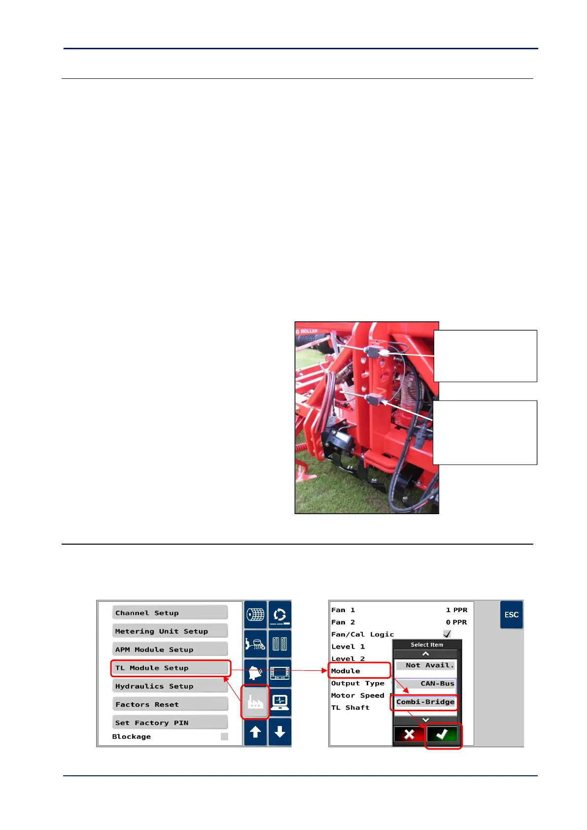
A typical Lift/lower finger switch installation on a
3-point linkage mounted drill would be as follows:
Note: Other switches/sensors can be used instead of finger
switches if preferred.
Route the ‘drill-lowered’ switch cable back to the
connector labelled ‘LOWER SWITCH CUTOUT’ on
the ISOBUS Artemis ECU harness.
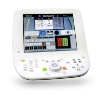
4.2.3 Tramline Module Configuration
If on starting the Artemis application, you get the alarm code “CODE H.1” “MODULE OFFLINE”, then you will need to
change the tramline module type to “Combi-Bridge”.
Go to the “Factory” menu > “TL Module Setup” > “Module”, and select “Combi-Bridge”.