ISOCAN / ISOBUS ARTEMIS - SEED DRILL CONTROLLER
21
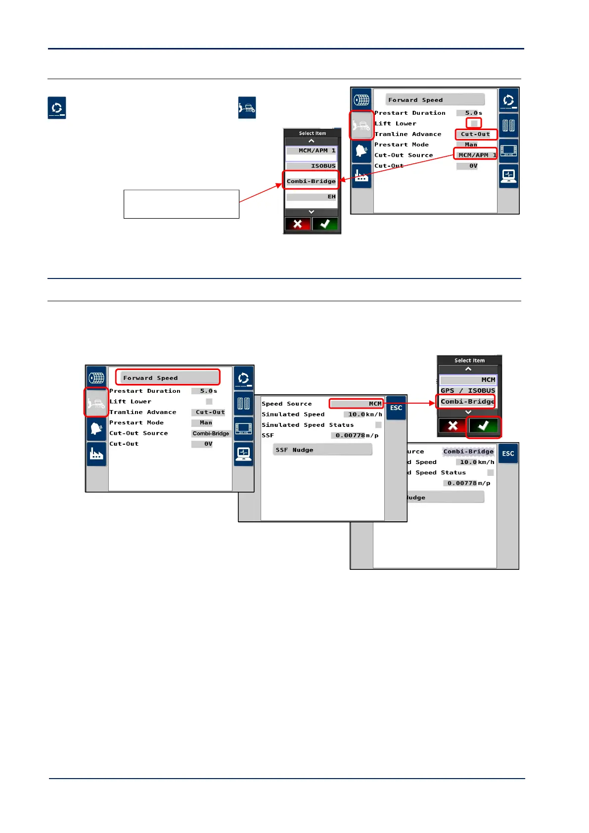
4.2.4 Area cutout / Lift-Lower / Tramline advance configuration
Setup in the Artemis app as follows.
1. Cycle to the ‘Setup’ screen and touch the tab.
2. Set “Tramline Advance” and set to “Cutout”.
3. If a ‘drill-lowered’ switch is installed for “Lift-Lower”
operation, then select “Lift/Lower” and set to “On”.
4. “Cutout Source” should always be “Combi-Bridge”.
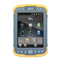
4.3 Forward Speed Input
4.3.1 Satspeed 2
The “Satspeed 2” converts a GPS NMEA VTG message to a pulse input = 0.0078 m/pulse (the same as an RDS radar
sensor input).
If the Forward speed signal input is from the RDS Satspeed interface [43], then set “Speed Source” in the Artemis app to
“Combi-Bridge” as follows,
Limitation
This unit should not be fitted in situations where speed measurement <0.5km/hr is required, or there is consistent
poor-quality GPS reception.
On initial power-up, it may take up to 5 minutes depending on the reception, to output a ground speed signal. When
used on a regular basis (daily or weekly), the startup time may be 1-2 minutes.
Bear in mind also, that the ground speed signal may be temporarily lost depending on the terrain and ground cover (e.g.
under or behind trees), and that this will be more prevalent in areas with weaker reception from a limited no. of
satellites.
Operation
The unit will automatically find the baud rate and depending on GPS reception status, provide a forward speed signal on
power up.
NOTE: The forward speed reading will default to zero below 0.5km/hr.