ISOCAN / ISOBUS ARTEMIS - SEED DRILL CONTROLLER
31
6.3.1 Sensor and Row numbering
Sensors are daisy-chained sequentially around the distribution head either CW or CCW.
The sensors are configured in the instrument with the corresponding row number that they are monitoring. When a
blockage or sensor fault occurs, the alarm screen will then indicate both the sensor no. and the row no. so that the
operator can quickly locate the fault.
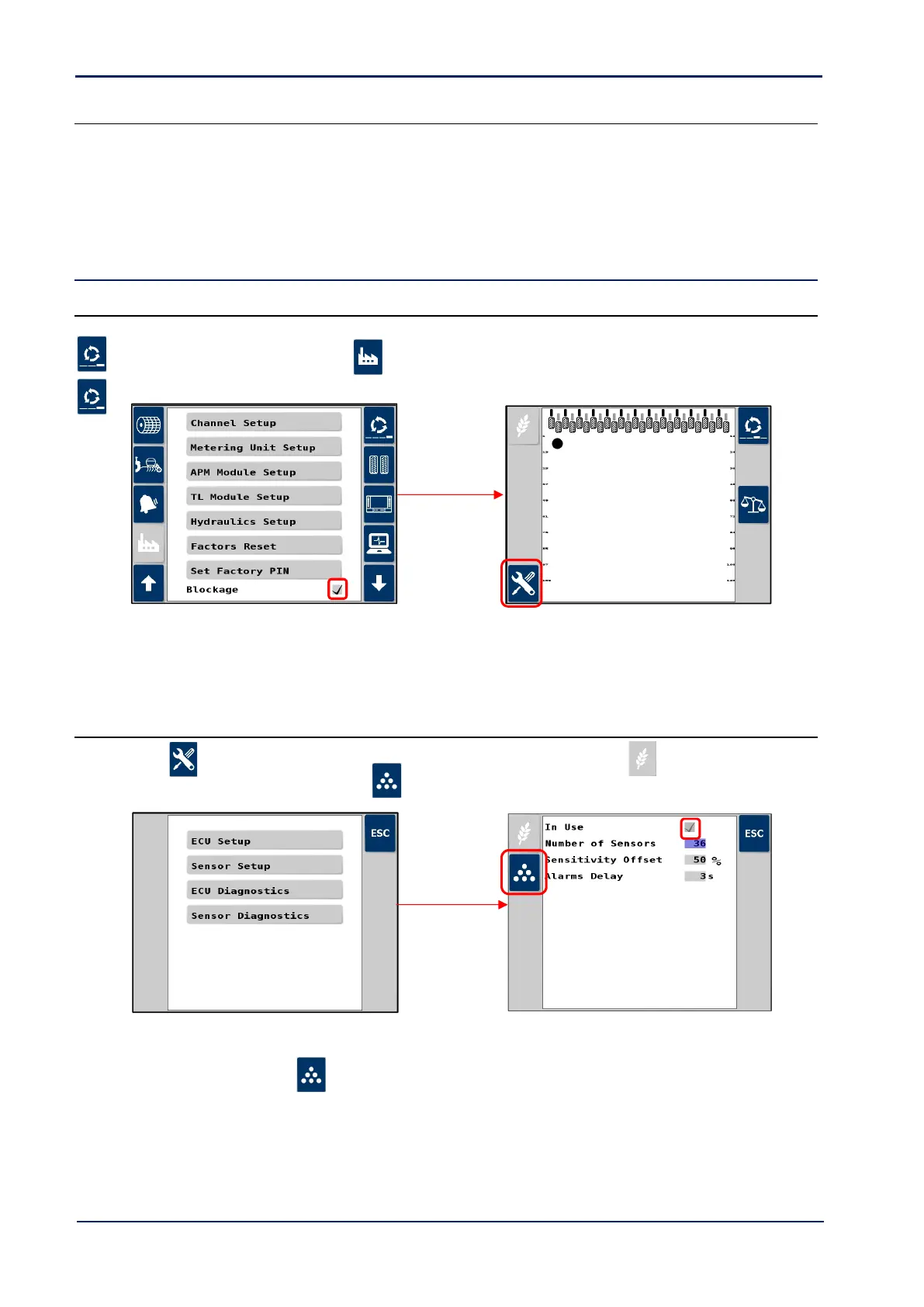
6.4 Blockage sensor configuration
6.4.1 Enable blockage monitoring functions
Setup in the Artemis app as follows.
1. Cycle to the ‘Setup’ screen, touch the tab, scroll down and select “Blockage” and tick box to enable.
2. Cycle to the Blockage Sensor screen that now appears as one of the primary screen pages.
NOTE: An error message may be generated reference connected sensors. Ignore it and continue below to set the number of
sensors after which the error should disappear.
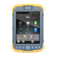
6.4.2 ECU Setup
3. Press , then select “1. ECU Setup”. By default, the single product ECU (i.e. seed ) is set to “On”.
4. To enable dual-product monitoring, press , and tick box to enable.
5. Enter the number of sensors.
6. Repeat for the fert sensors ( ) as necessary.