Rev. E
Groundsmaster 4000--D Hydraulic System (Rev. B)Page 4 -- 69
5. Visually inspect cartridge valve for damaged sealing
surfaces and contamination.
A. Contamination may cause valves to stick or hang
up. Contamination can become lodged in small valve
orifices or seal areas causing malfunction.
B. If valve sealing surfaces appear pitted or dam-
aged, the hydraulic system may be overheating or
there may be water in the system.
CAUTION
Use eye protection such as goggles when using
compressed air.
6. Clean cartridge valve using clean mineral spirits.
Submerge valve in clean mineral spirits to flush out con-
tamination. Particles as fine as talcum powder can affect
the operation of high pressure hydraulic valves. If c ar-
tridge design allows, use a wood or plastic probe to push
the internal spool in and out 20 to 30 times to flush out
contamination. Be extremely careful not to damage car-
tridge. Use compressed air for cleaning.
7. Reinstall the cartridge valve:
A. Lubricate new seal kit components with clean hy-
draulic oil and install on valve. The o--rings, sealing
rings, and backup rings must be arranged properly
on the cartridge valve for proper operation and seal-
ing.
IMPORTANT: Use care when handling the valve car-
tridge. Slight bending or distortion of the stem tube
can cause binding and malfunction.
B. Thread cartridge valve carefully into manifold
port. The valve should go in easily without binding.
C. Torque cartridge valve using a deep socket to val-
ue identified in manifold illustration.
D. If cartridge is solenoid operated, carefully install
solenoid coil to the cartridge valve. Apply “Loctite
242” or equivalent to the threads of the valve. Torque
nut to value identified in manifold illustration.
8. If problems still exist, remove valve and clean again
or replace valve.
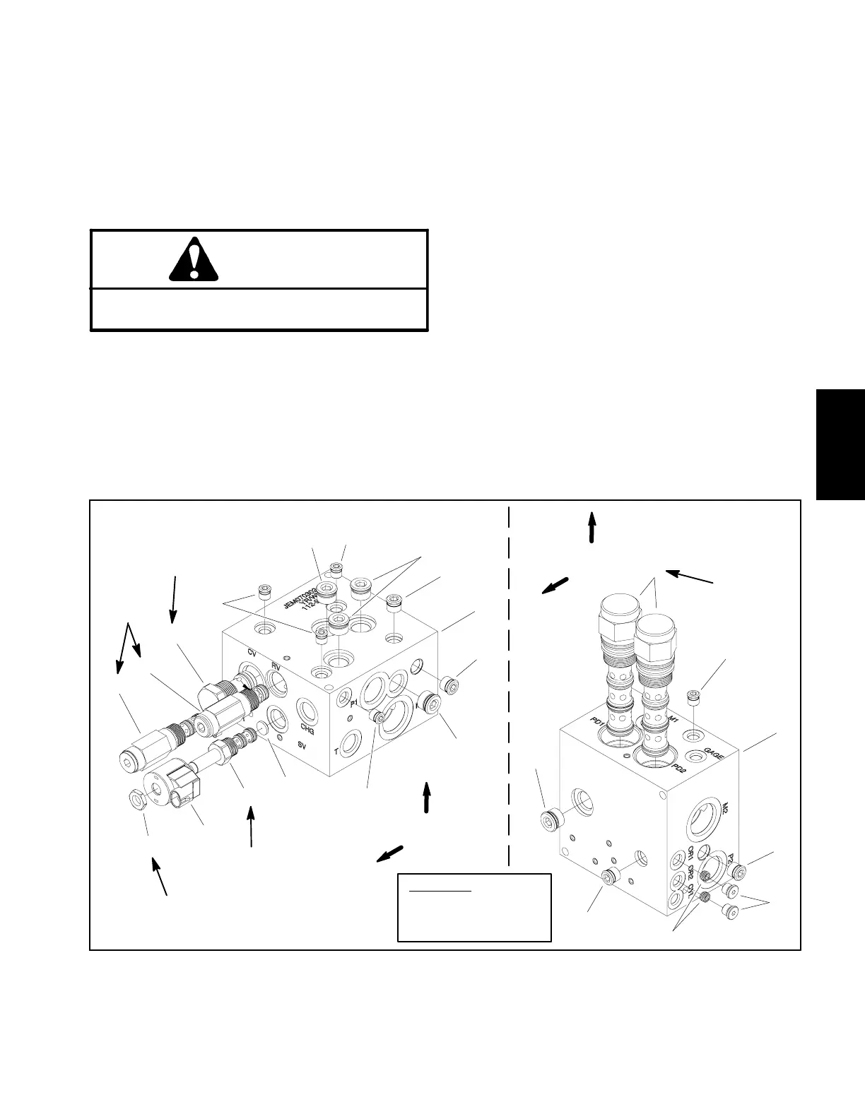
1. Manifold body
2. Solenoid valve (port SV)
3. Solenoid coil
4. Check valve (port CV)
5. Nut
6. Directional valve (ports PD1 & PD2)
7. Pressure reducing valve (port PR)
8. Relief valve (port RV)
9. Orifice (.030)
10. #4 zero leak plug with O--ring
11. #6 zero leak plug with O--ring
12. Orifice (.050)
13. #8 zero leak plug with O--ring
Figure 51
25 ft--lb
(34 N--m)
35 ft--lb
(47 N--m)
20 ft--lb
(27 N--m)
50 ft--lb
(67 N--m)
5 ft--lb
(6.7 N--m)
FRONT
UP
7
13
10
8
2
3
1
11
9
4
5
13
13
11
10
10
6
12
11
13
10
1
11
10
PLUG TORQUE
#4 Zero Leak: 20 ft--lb (27 N --m)
#6 Zero Leak: 25 ft--lb (34 N --m)
#8 Zero Leak: 50 ft--lb (67 N --m)
DOWN
REAR
JEM MANIFOLD
Hydraulic
System