Groundsmaster 4000--D/4010--D Page 5 -- 61 Electrical System
Hydraulic Oil Temperature Sender
The Groundsmaster 4000--D and 4010--D use a temper-
ature sender as an input for the TEC controller t o identify
if the hydraulic oil temperature has reached an exces-
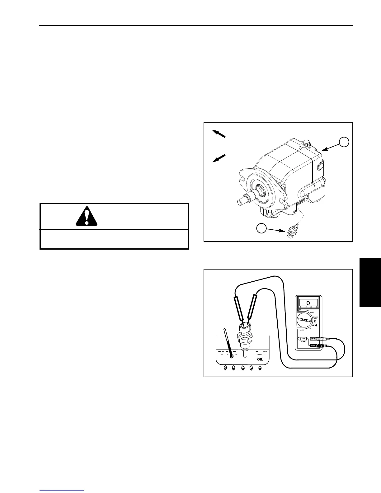
sive level. The hydraulic oil temperature sender is at-
tached to the bottom of the rear axle motor (Fig. 82).
The InfoCenter will display fault code 18 if the hydraulic
oil temperature sender inputs to the TEC controller are
not in the normal range.
Testing
1. Locate temperature sender in rear axle motor. Dis-
connect wire harness connector from sender.
2. Place suitable drain pan under temperature sender
in rear axle motor. Thoroughly clean area around tem-
perature sender and remove sender from axle motor.
3. Put sensing end of sender in a container of oil with
a thermometer and slowly heat the oil ( Fig. 83).
CAUTION
Handle the hot oil with extreme care to prevent
personal injury or fire.
NOTE: Prior to taking resistance readings with a digital
multimeter , short the meter test leads together. The me-
ter will display a small resistance value (usually 0.5
ohms or less). This resistance is due to the internal re-
sistance of the meter and test leads. Subtract this value
from from the measured value of the component you are
testing.
4. Check r esistance of the sender with a multimeter
(ohms setting) as the oil temperature increases.
A. The meter should indicate from 11.6 to 13.5 kilo
ohms at 68
o
F(20
o
C).
B. The meter should indicate from 2.3 to 2.5 kilo
ohms at 140
o
F(60
o
C).
C. The meter should indicate from 605 to 669 ohms
at 212
o
F(100
o
C).
D. Replace sender if specifications are not met.
5. After allowing the sender to cool, install sender:
A. Install new O--ring on sender.
B. Install sender into port and torque from 9to11ft--
lb(12.3to14.9N--m).
C. Connect wire harness connector to sender.
6. Check and fill hydraulic system to proper level.
Figure 82
1. Rear axle motor 2. Oil temp sender
FRONT
RIGHT
1
2
Figure 83
Electrical
System

 Loading...


