Groundsmaster 4000−DPage 7 − 12Chassis
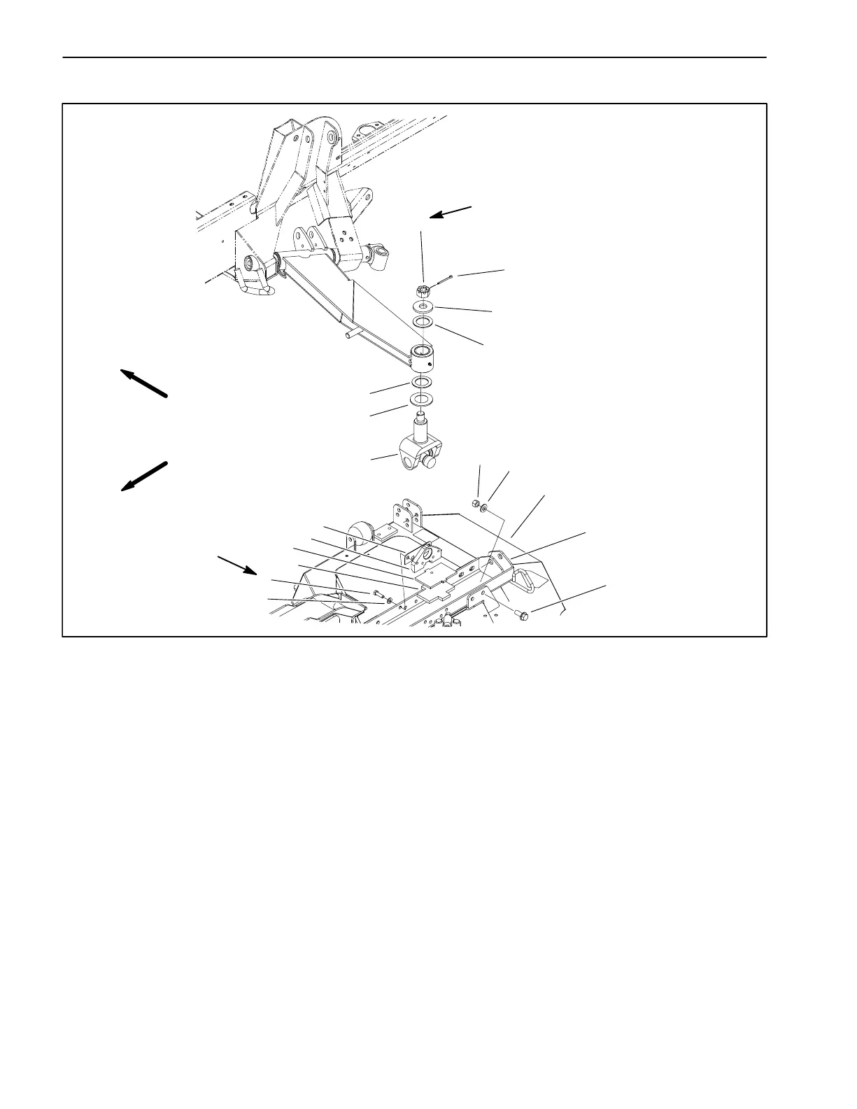
Lift Arm Yoke Joint
1. Side cutting deck (LH shown)
2. Deck mount (LH shown)
3. Shim
4. Base mount
5. Plate
6. Rubber pad
7. Cap screw
8. Flat washer
9. Yoke joint
10. Spacer
11. Thrust washer
12. Hardened washer
13. Cotter pin
14. Slotted hex nut
15. Flange head screw
16. Flat washer
17. Lock nut
Figure 11
9
10
11
13
12
2
14
5
6
7
8
3
4
1
11
FRONT
RIGHT
150 to 180 ft−lb
(203 to 244 N−m)
27 to 33 ft−lb
(37 to 44 N−m)
17
16
15
Removal
1. Park machine on a level surface, lower cutting units,
stop engine, engage parking brake, and remove key
from the ignition switch.
2. Remove eight flange head screws, flat washers, and
lock nuts that secure deck mount to cutting deck.
3. Remove cotter pin from yoke joint shaft. Make sure
that deck mount is supported and remove slotted hex
nut that secures yoke joint to lift arm. Take hardened
washer and thrust washer from yoke joint shaft. Raise
lift arm enough to free yoke joint from lift arm. Remove
second thrust washer and spacer washer from yoke
shaft.
4. Remove cap screws and flat washers that secure
base mounts to deck mount.
5. Lift yoke joint and base mounts from deck mount. Re-
move shims, plate, and rubber pad from deck mount.
6. Press yoke joint from base mounts.
Yoke Joint Disassembly
1. Remove snap rings from yoke (Fig. 12).
IMPORTANT: Support yoke when removing and
installing cross and bearings to prevent yoke dam-
age.
2. Use a press to remove cross and bearing assembly
from yoke.