Note:Replacethegasketorscreenorbothifthese
partsarewornordamaged
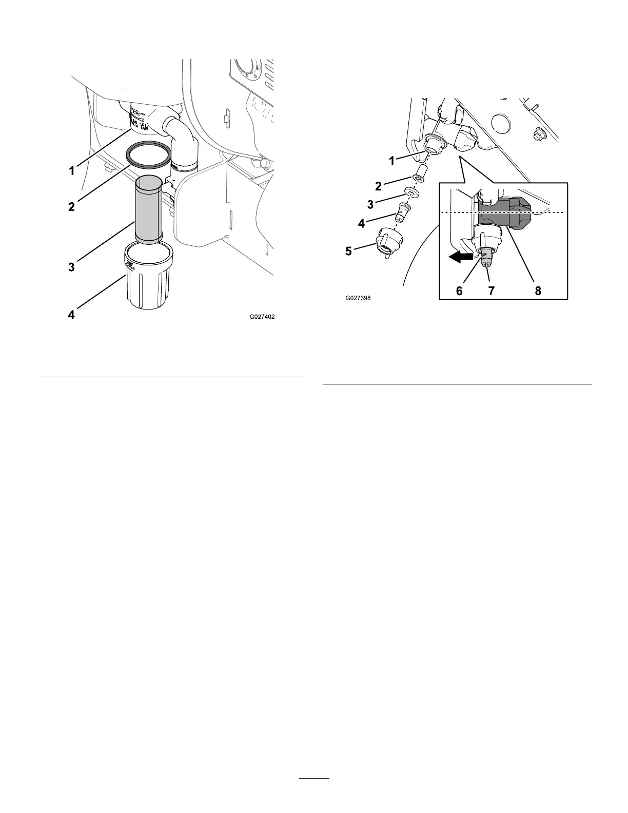
Figure48
1.Strainerbody3.Screen
2.Gasket
4.strainerbowl
5.Allowanyresidualchemicalsolutiontodrainfromthe
strainerbody.
Note:Disposeofthewastesolutionaccordingtolocal
codesandthechemicalmanufacturer'sinstructions.
6.Useasoft-bristlebrushandcleanwatertocleanthe
screenandbowl
7.Installthescreenintothestrainerbody(.Figure48).
8.Installthestrainerbowlontothestrainerbodyand
handtightenthebowl(Figure48).
9.Rotatethehandleforthesupplyvalve90°clockwise
(Figure47).
CleaningtheSprayerNozzle
ServiceInterval:Aftereachuse
1.Rotatethenozzlecap90°counterclockwiseand
removethecapfromthenozzlebody(Figure49).
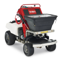
Figure49
1.Nozzlebody5.Nozzlecap
2.Strainer
6.Atomizer
3.Gasket7.Slot
4.Sprayertip
8.Regulatorcase
2.Removethesprayertip,gasket,andstrainerfromthe
nozzlebody(Figure49).
Note:Replaceanywornordamagednozzleparts.
3.Useasoft-bristlebrushandcleanwatertocleanthe
nozzletip,gasket,andstrainer.
4.Assemblethestrainerintothenozzlebody(Figure49).
5.Assemblethesprayertipandgasketintothenozzle
cap(Figure49).
6.Installthetip,gasket,andcapontothenozzlebody
(.Figure49).
Note:Usetheslottorotatetheatomizer(Figure49)of
thesprayertipforward(in-linewiththeow-regulator
caseofthenozzlebody).
7.Rotatethenozzlecap90°clockwise(Figure49).
8.Repeatsteps1through7forthe2othersprayer
nozzles.
42