ProcedureforGearPumpFlowTest(continued)
#4 Deck #1 Deck #5 Deck
#7 Deck
(GM4700)
#6 Deck
(GM4700)
#3
Deck
#2
Deck
g308386
Figure92
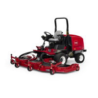
CUTTINGDECKLOCATIONS
4.Determinewhichgearpumpsectionistobetested.Disconnecthydraulic
hosefromttingingearpumpsectionthatistobetested(Figure91).
5.Installtester(owandpressure)inserieswiththedisconnectedhoseand
hydraulicttingingearpumpsection.
6.Makesuretheowcontrolvalveontesterisfullyopen.
7.Startengineandincreaseenginespeedtohighidlespeed.Donotengage
thecuttingdecks.
IMPORTANT
Donotfullyrestrictoilowthroughtester.Inthistest,theowtester
ispositionedbeforethereliefvalve.Pumpdamagecanoccurifthe
oilowisfullyrestricted.
8.Watchpressuregaugecarefullywhileslowlyclosingtheowcontrolvalve
until69bar(1000PSI)isobtained.VerifywiththeInfoCenterdisplaythatthe
engineisstillrunningatthecorrecthighidlespeed.
Note:Ifenginespeeddropsduringtesting,pumpowwilldecreaseand
owtestresultswillbeinaccurate.
9.Normalowindicationforthefour(4)gearpumpsectionsislistedinbelow
table:
PUMPSECTIONNORMALFLOWMINIMUMFLOW
FIRSTSECTION41.6LPM(11GPM)34LPM(9GPM)
SECONDSECTION41.6LPM(11GPM)34LPM(9GPM)
THIRDSECTION22.7LPM(6GPM)18LPM(4.8GPM)
FOURTHSECTION22.7LPM(6GPM)18LPM(4.8GPM)
10.Shutoffengineandrecordtestresults.
11.Ifapressureof69bar(1000PSI)cannotbeobtainedorowwaslessthan
theminimumowlistedinabovetable,checkforrestrictioninthepump
HydraulicSystem:Testing
Page5–84
Groundsmaster
®
4500-D/4700-D
19245SLRevA

 Loading...


