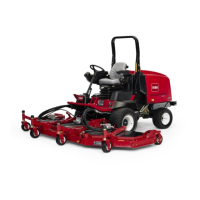
FanControlManifold
g308970
Figure139
1.Fancontrolmanifold6.Deckmanifold(GM4500-Dshown)
11.Hydraulictube
2.Supportbracket
7.Hydraulichose12.Hydraulictube
3.Flangeheadscrew(2used)
8.Hydraulichose13.Hydraulictube
4.Batterysupport9.Hydraulictube
5.Aircleanermount10.Hydraulictube
Removal(Figure139)
Theportsonthefancontrolmanifoldaremarkedforeasyidenticationof
components.Example:P1isthegearpumpconnectionport(seeAppendixA
(pageA–1)toidentifythefunctionofthehydrauliclinesandcartridgevalves
ateachmanifoldport).
1.Parkmachineonalevelsurface,lowercuttingdecks,stopengine,apply
parkingbrakeandremovekeyfromtheignitionswitch.
2.ReadtheGeneralPrecautionsforRemovingandInstallingHydraulicSystem
Components(page5–87).
3.Unlatchandraisehood.
4.Topreventcontaminationofhydraulicsystemduringfancontrolmanifold
removal,thoroughlycleanexteriorofmanifold.
5.Labelwireharnesselectricalconnectorsthatattachtomanifoldsolenoid
coils.Disconnectconnectorsfromthesolenoidcoils.
6.Disconnecthydrauliclinesfrommanifoldandputcapsorplugsonopen
hydrauliclinesandttings.Labeldisconnectedhydrauliclinesforproper
assembly.
HydraulicSystem:ServiceandRepairs
Page5–152
Groundsmaster
®
4500-D/4700-D
19245SLRevA

 Loading...


