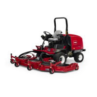
Removal(Figure155)(continued)
4.Disconnecthydraulichosesfromliftcylinder.Putcapsorplugsonopen
hydraulichosesandttingstopreventsystemcontamination.Labelthe
hydraulichosestoshowtheircorrectpositionontheliftcylinderforassembly
purposes.
5.Removelocknuts(item2)thatsecurelinkassembly(item4).Removerear
link(item3)fromlinkassembly.Pulllinkassemblyfromliftarmassembly,
liftlinks(item13)andcylindershaftcleviswhichwillfreeliftcylinderfromlift
arm.Locateandremoveplasticrollers(item5)positionedonbothsides
ofcylinderclevis.
6.Removeoneretainingringthatsecuresthecylinderpin(item7)totheliftarm
support.Pullpinfromliftarmandcylinderbarrelclevis.
#4 Deck #1 Deck #5 Deck
#7 Deck
(GM4700)
#6 Deck
(GM4700)
#3
Deck
#2
Deck
g308386
Figure156
CUTTINGDECKLOCATIONS
7.Removeliftcylinderfrommachine.
8.Ifhydraulicttingsaretoberemovedfromliftcylinder,markttingorientation
toallowcorrectassembly.RemovettingsfromcylinderanddiscardO-rings.
Note:Forliftcylinderdisassemblyandassemblyprocedures,seeLift
CylinderService(page5–173).
Installation(Figure155)
1.Ifttingswereremovedfromliftcylinder,lubricateandplacenewO-ringsonto
ttings.Installttingsintocylinderopeningsusingmarksmadeduringthe
removalprocesstoproperlyorientatettings.Tightenttings(seeInstalling
theHydraulicFittings(SAEStraightThreadO-RingFittings)(page5–9)).
2.Positioncylinderbarrelclevistoliftarmandinsertcylinderpin(item7)intolift
armsupportandcylinderclevis.Securepinwithretainingring(item6).Make
surethatretainingringisfullyinstalledingrooveinpin.
3.Positionplasticrollers(item5)tocylindershaftclevis.Insertlinkassembly
(item4)throughliftarmassembly,liftlinks(item13),plasticrollersand
cylindershaftclevis.Installrearlink(item3)tolinkassemblyandsecure
assemblywithlocknuts(item2).
4.Removecapsandplugsfromhydraulichosesandttings.Attachhosesto
liftcylinderttings(seeInstallingHydraulicHosesandTubes(O-RingFace
Seal)(page5–7)).
5.Fillreservoirwithhydraulicuidasrequired.
Groundsmaster
®
4500-D/4700-D
Page5–171
HydraulicSystem:ServiceandRepairs
19245SLRevA

 Loading...


