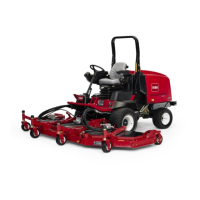
Assembly(Figure280)
1.AssembletractionpedalusingFigure280,Figure281andFigure282as
guidesnotingthefollowingitems:
A.ApplygreasetoboththeODandIDofthespringretainer(item23in
Figure280)beforeinstallation.T akecaretonotgetgreaseonthreads
ofspringshaft(19)orjamnut(9).
B.Iftractionpivotshaft(27)wasremoved,applygreasetotheshaftareas
thatwillbeinsidethebearingsafterassembly.
C.Wheninstallingrollpins(11,17,21and28),makesuretosupportshaftto
preventcomponentdamage.Useapresstoinstallrollpins.Also,take
caretonotdistortrollpinsduringassembly.
D.Makesurethatrollpin(17)isfullyinsidethebutterygrooveofthehub
(30).Therollpinshouldnotcontactthehubthroughouttheoperating
range.
E.Toinstallthetractionpedalpositionsensor(29),aligntheslotontheend
ofthetractionpivotshaftwiththeslotinthepositionsensor.Holdposition
sensorinpositionwhileinstallingstandoffspacers(16),captureplate
(32)andcapscrews(33).
F.Leavethejamnut(9)loosesothatthepositionsensorcanbecalibrated.
2.Aftertractionpedalassembly,makesurethatthereisnobindinginpedal
movementandalsothatpedalreturnstothecenteredpositionwhen
released.Correctanystickingorbindingbeforemachineoperation.
3.Plugmachinewireharnessconnectorintotractionpedalpositionsensor(29).
4.Afterassemblyofthetractionpedal,calibratethetractionpedalposition
sensorusingtheInfoCenterdisplay(seeTractionPedalPositionSensor
Calibration(page6–21)).
5.Makesurethatjamnut(9)istightenedafterpositionsensoradjustment.
Groundsmaster
®
4500-D/4700-D
Page8–9
Chassis:ServiceandRepairs
19245SLRevA

 Loading...


