g026250
Figure5
1.Insulatorboot(positive
batterycable)
3.Negativebatterycable
(black)
2.Negativebatterypost
4.Slidetheinsulatorbootoverthepositive
terminal.
Note:Theinsulatorbootpreventsapossible
short-to-groundfromoccurring.
5.Connectthenegativebatterycable(black)tothe
negative(–)terminalofthebatteryandsecure
thecablewithboltsandnuts.
6.Alignthebatterycovertothebatterybase
(Figure4).
7.Squeezethebatterycover,alignthetabsto
thebatterybase,andreleasethebatterycover
(Figure4).
3
CheckingtheFluidLevels
andTirePressure
NoPartsRequired
Procedure
1.Checktheengine-oillevelbeforeandafter
yourststarttheengine;refertoCheckingthe
Engine-OilLevel(page41).
2.Checkthetransmission-uidlevelbeforeyou
rststarttheengine;refertoCheckingthe
Transmission-FluidLevel(page49).
3.Checktheengine-coolantlevelbeforeyou
rststarttheengine;refertoCheckingthe
Engine-CoolantLevel(page53).
4.Checkthebrake-uidlevelbeforeyourststart
theengine;refertoCheckingtheBrake-Fluid
Level(page56).
5.Checktheairpressureinthetires;referto
CheckingtheTirePressure(page21).
4
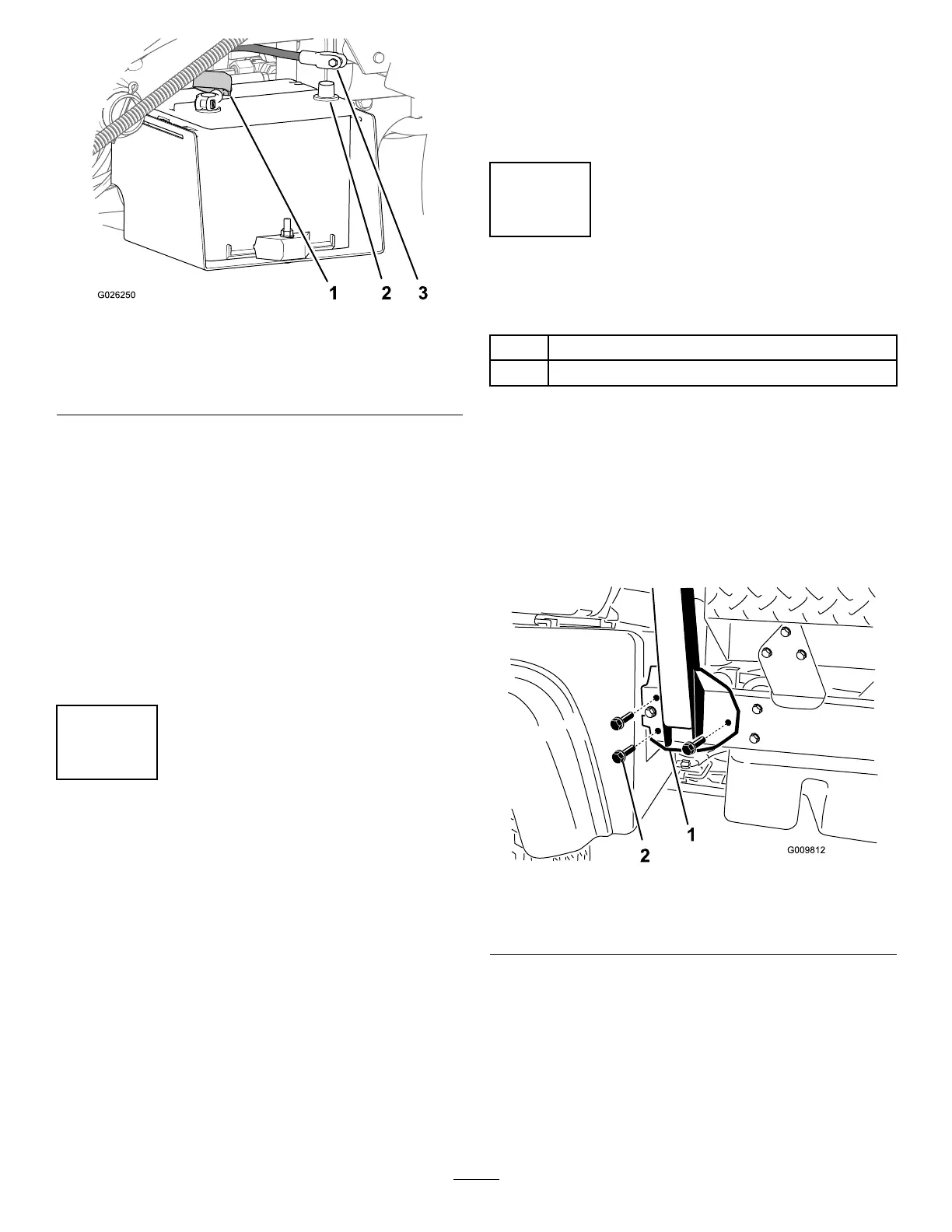
InstallingtheRollBar
Partsneededforthisprocedure:
1Rollbar
6
Flange-headbolt(1/2x1-1/4inches)
Procedure
1.Applymedium-grade(service-removable)
thread-lockingcompoundtothethreadsofthe6
ange-headbolts(1/2x1-1/4inches).
2.Aligneachsideoftherollbarwiththemounting
holesoneachsideofthemachineframe(Figure
6).
g009812
Figure6
1.Rollbarmountingbracket
2.Flange-headbolt(1/2x
1-1/4inches)
3.Securetherollbarmountingbrackettothe
machineframeusing3ange-headbolts(1/2x
1-1/4inches)oneachside(Figure6).
4.Torquetheange-headbolts(1/2x1-1/4inches)
to115N∙m(85ft-lb).
13