g002370
Figure32
1.Wearblock
3.Carriagebolt
2.Spacerbracket
1.Ensurethattheliftcylindersarefullyretracted.
2.Carefullysetthebedontothemachineframe,
aligningtherearbedpivot-plateholeswiththe
holesintherearframechannel,andinstallthe2
clevispinsandlynchpins(Figure32).
3.Withthebedlowered,secureeachcylinderrod
endtotheappropriateslotsinthebed-mounting
plateswithaclevispinandlynchpin.
4.Inserttheclevispinfromoutsideofthebedwith
thelynchpinorientedtowardtheoutside(Figure
32).
Note:Therearslotsareforafullbed
installation;thefrontslotsarefora2/3-fullbed
installation.
Note:Youmayneedtostarttheengineto
extendorretractthecylindersforalignmentwith
theholes.
Note:Youcanplugtheunusedslotwithabolt
andnuttopreventassemblyerrors.
5.Starttheengineandengagethehydraulic-lift
levertoraisethebed.
6.Releasetheliftleverandshutofftheengine.
7.Installthebed-safetysupporttoprevent
accidentallyloweringthebed;refertoUsingthe
BedSupport(page35).
8.Installthelynchpinstotheinsideendsofthe
clevispins.
Note:Iftheautomatictailgatereleaseis
installedonthebed,ensurethatthefrontdump
linkrodisplacedontheinsideoftheleftclevis
pinbeforeyouinstallthelynchpin.
RaisingtheMachine
DANGER
Amachineonajackmaybeunstableandslip
offthejack,injuringanyonebeneathit.
•Donotstartthemachinewhilethemachine
isonajack,astheenginevibrationor
wheelmovementcouldcausethemachine
toslipoffthejack.
•Alwaysremovethekeyfromthekeyswitch
beforegettingoffthemachine.
•Blockthetireswhenthemachineisona
jack.
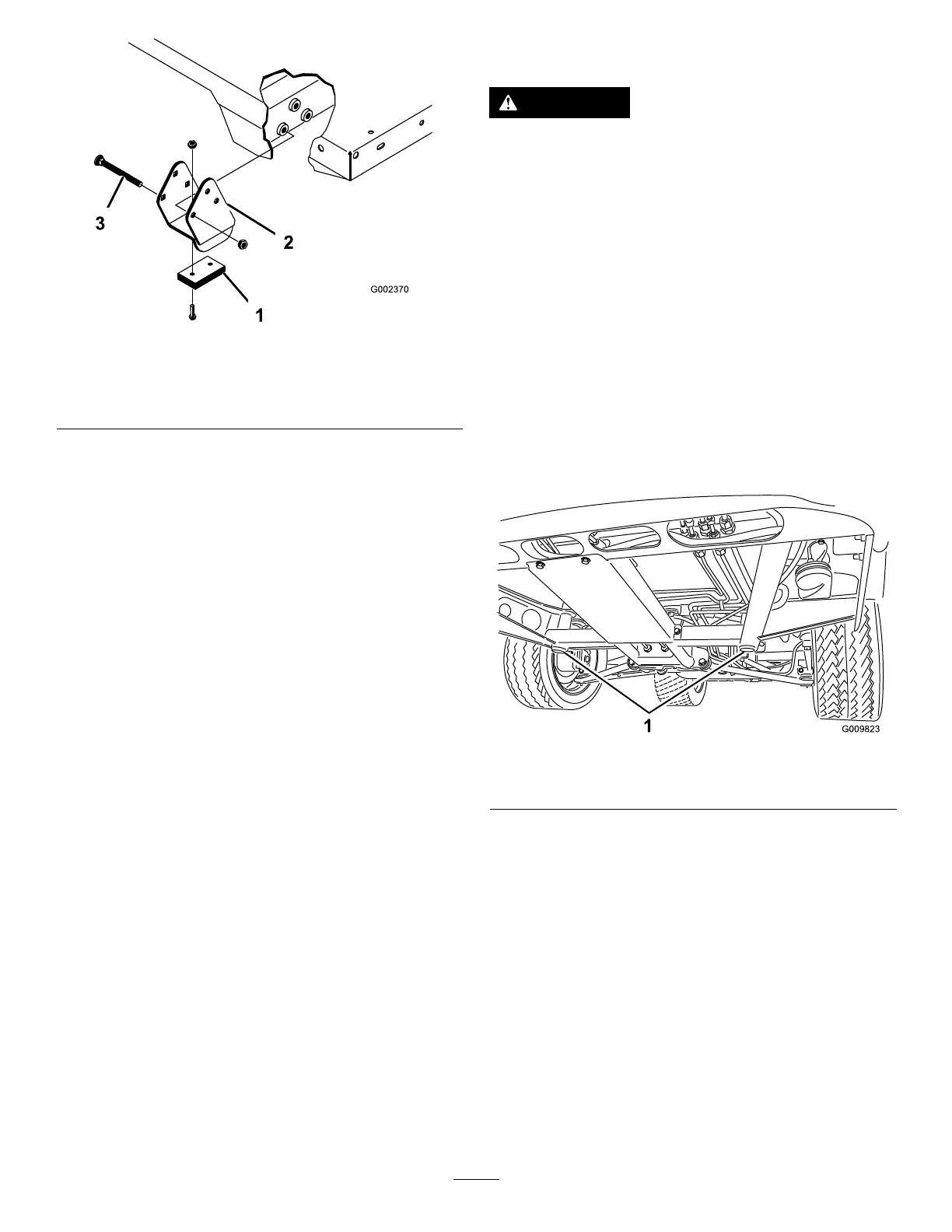
Whenjackingupthefrontofthemachine,always
placeawoodenblock(orsimilarmaterial)between
thejackandthemachineframe.
Thejackingpointatthefrontofthemachineislocated
underthefront,centerframesupport(Figure33).
g009823
Figure33
1.Frontjackingpoints
Thejackingpointattherearofthemachineislocated
undertheaxle(Figure34).
37